WEB BDT V1.0.0

Chinese    Off-line for Windows    BDT for Windows    Driver for WEB BDT    Firmware for Burning EVK    Script for Llnux    Download PDF   

Menu

1. Introduction

1.1 Overview of functions

2. Operation guide

2.1 Preparation

2.1.1 Hardware connection
2.1.2 Driver update
2.1.3 Device connection

2.2 Firmware download

2.2.1 Download firmware to Flash
2.2.2 Download firmware to SRAM

2.3 Erase Flash

2.4 Activate MCU

2.5 Debug

2.5.1 Data read and write

2.5.1.1 Data read
2.5.1.2 Data write

2.5.2 Parsing of disassembly files

2.5.3 Debug MCU

2.5.3.1 Run MCU
2.5.3.2 Pause MCU
2.5.3.3 Trace PC
2.5.3.4 Step MCU
2.5.3.5 Stall MCU
2.5.3.6 Start MCU

2.6 SWS

2.7 Multi-address download

2.8 Firmware upgrade

2.9 File upload

3. Standalone WEB BDT

4. Windows for BDT


1. Introduction

Telink "WEB BDT (Burning and Debugging Tool)" is suitable for downloading and debugging of all Telink chips. This document describes how to use "WEB BDT".

1.1 Overview of functions

During the development process, the firmware can be downloaded to the target board by using BDT. Its main functions include: flash erasing, firmware downloading, chip activation, reading and writing global variables, displaying variable list, single-step debugging, reading PC value, stalling and starting the chip, online or local multi-firmware multi-address download, online or local "Burning EVK" firmware update, uploading files to server, and so on. The "WEB BDT" supports Windows, MAC, Android, Linux, and the following browsers:

2. Operation guide

2.1 Preparation

2.1.1 Hardware connection

Use the Telink "Burning EVK" to connect the target board to the PC (or tablets and cell phones).

  • Connect the "Burning EVK" to the PC via USB cable. Observe the indicator light, if there is only one light on, it means the connection between "Burning EVK" and PC is normal (if not, try to update the latest "Burning EVK" firmware).
  • To connect the target board to the "Burning EVK", there are two methods: 1) Connect the target board directly to the "Burning EVK" via the USB port as shown in the following figure. This connection method is only applicable to MCU with USB interface and support USB function, such as a dongle board. 2) Connect the target board to the "Burning EVK" via a single wire Swire interface, as shown in the figure below.

2.1.2 Driver update

Before connecting the device, please update the latest firmware of "Burning EVK", and then install the USB driver.   Driver for WEB BDT    Firmware for Burning EVK    Observe the "Burning EVK" indicator, if only one light (green or blue) is on, you don't need to update the firmware, if not, update the firmware first as below.
In Linux systems (Ubuntu for example), the default kernel driver needs to be separated. After plugging in the USB, you need to enter the "/sys/bus/usb/drivers/usblp/" directory, use "ls" command to view the contents of the folder. You can see the file name composed of numbers and symbols, such as "1-2.3:1.0", execute the command "su root" and enter the password, then enter echo "1-2.3:1.0" > unbind command, you can finish the setting. Every time you plug and unplug the USB, you have to perform the above operations. The above is the current plan, a more convenient plan is expected to be released in the near future.

      In Linux system (taking Ubuntu as an example), copy the file 60-webbdt.rules to/etc/udev/rules.d/60-webbdt.rules, and use dos2unix to change the end character of the file to UNIX mode

$ sudo cp 60-webbdt.rules /etc/udev/rules.d/60-webbdt.rules $ sudo apt-get install -y dos2unix $ sudo dos2unix /etc/udev/rules.d/60-webbdt.rules

Then copy unbind.sh to /usr/binand change the permission:

$ sudo cp unbind.sh /usr/bin/unbind.sh $ sudo chmod a+x /usr/bin/unbind.sh $ sudo dos2unix /usr/bin/unbind.sh

Then reload udev:

sudo udevadm control --reload

Just plug and unplug, and you won't need to do any manual processing in the future.

After updating the firmware, power off and reboot "Burning EVK", switch to blue light steady on state via sw2 (you can use web BDT in blue light steady on state, and switch to green light steady on state to use BDT on windows end normally). After switching to the blue light steady on, open Zadig software and click the "List All Devices" option under the Options menu, select Telink WEB Debugger, click Reinstall WCID Driver, wait for the prompt of converting successfully, then power off and reboot the "Burning EVK".

After finishing the driver update, the first time switching to green light (for BDT at Windows end), follow these steps to set the driver: open Device Manager, click "Update Driver", click "Browse My Computer" to find the driver, click "Let me select from the list of available drivers" on the computer, select USB print support. Every time you switch the status via sw2, you need to plug and unplug the USB cable after the switching so as to reboot "Burning EVK" to take effect the settings.

2.1.3 Device connection

Click Connect in the drop-down menu of Device, the browser will pop up the choice of device connection, select Telink Web Debugger device and click Connect (if there are multiple "Burning EVK" connections, there will be multiple Telink Web Debugger devices in the pop-up list, please select the devices you want to connect).

2.2 Firmware download

Before downloading the firmware, please make sure that the target board and the computer are properly connected via "Burning EVK" and can communicate with each other.

2.2.1 Download firmware to flash

The user can follow the guidelines in this section to download the firmware into the flash address space specified in the target board. 1) Click on the chip selection drop-down menu and select the chip model of the target board, the default is B91. 2) In the "Setting" tab, enter the first address (in hexadecimal) of the flash download in the Download Addr:0x input box, for example, 0 (default first address is 0) or 20000 (first address is 0x20000). 3) Select Flash (default) in the Flash/SRAM checkbox. 4) Click the "File Import" button to select the firmware file to be downloaded to the target board. The name of the file and the time it was created will be printed in the log window below, and the file name will be displayed on the "File Import" button. 5) Check the connection between the target board and the computer. If it is not yet connected or it is disconnected, you can connect them again. 6) Click the Download button to download the selected firmware to the set flash address, and the log window will display the corresponding log information. 7) Reset the MCU to allow the newly downloaded program to run without powering off the MCU. The user can follow either of the two methods below to reset the MCU.

  • If manual mode is selected in the manual mode/auto mode checkbox, the user needs to reset the chip manually by clicking the Reset button after download.
  • If auto mode is selected in the manual mode/auto mode checkbox, the device will be automatically reset after download.

2.2.2 Download firmware to SRAM

The process of downloading firmware to SRAM is similar to downloading to flash, except that you need to select SRAM (default is flash) in the Flash/SRAM checkbox. And you need to enter the first address (in hexadecimal) of SRAM download in the Sram Start Addr:0x input box, for example, c0000000 (0xc0000000, the default first address of B91) or c0002000 (the first address is 0xc0002000). A demonstration of downloading the program into the SRAM of the B91 chip and automatically resetting is shown below.

2.3 Erase Flash

The flash erase function is used to erase the specified flash address in 4KB unit, users can follow the steps below. 1) In the Erase Flash Addr:0x input box, set the starting address (in hexadecimal) of the flash space to be erased, fox example, 0 (default first address is 0) or 2000 (first address is 0x2000). 2) In the Sector Erase Size(K) input box, set the size of the flash space to be erased (in decimal), for example, 512 (default erase size is 512KB) or 1024 (erase size is 1024KB). 3) Click the "Erase" button to start erasing the specified flash space of the target board. Erasing the 512KB size of flash in the B91 chip starting from address 0 is shown in the following figure.

2.4 Activate MCU

When the PC fails to communicate with the target board (e.g. the chip enters low power mode), you can activate the chip by clicking the Activate button. When the activation is successful, the log window will print "Activate OK!", and when it fails, it will print "Activate failed!".

2.5 Debug

2.5.1 Data read and write

2.5.1.1 Data read

1) Select the corresponding chip model. 2) Click the "Access Memory" tab. 3) In the input box "Address:0x", enter the address (in hexadecimal), e.g. 80000 (0x80000). 4) In the input box "Length:0x", enter the number of bytes to be read (in hexadecimal), e.g. 10 (0x10). 5) Click the "usb read" button to read the data of "Burning EVK" (the starting address and size are set by the above steps), click the "evk read" button to read the data of the target board (the starting address and size are set by the above steps).
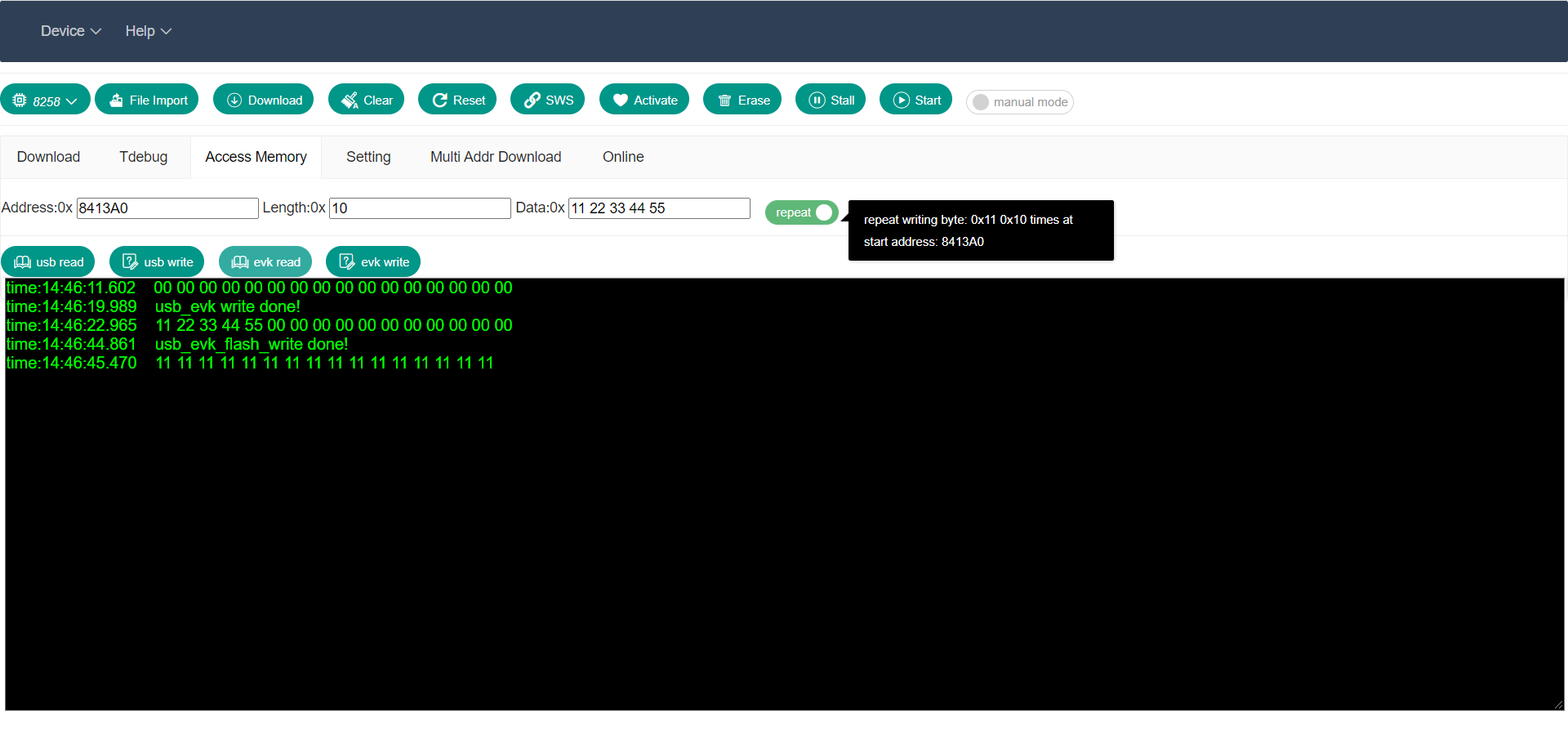
2.5.1.2 Data write

1) Select the corresponding chip model. 2) Click the "Access Memory" tab. 3) In the input box "Address:0x", enter the address (in hexadecimal), e.g. 80000 (0x80000). 4) In the input box "Length:0x", enter the number of bytes to be written (in hexadecimal), for example 10 (0x10). 5) In the "Data:0x" box, enter the data to be written. 6) In the normal/repeat checkbox, you can select the mode of writing data. Normal mode: write the data in the Data input box to the starting address; repeat mode: write the first data in the Data input box to the starting address, and the number of writes is the number of inputs in the Length input box. 7) Click "usb write" button to write data to "Burning EVK" (data, starting address and size are set by the above steps), click "evk write" button to write data to the target board (data, starting address and size are set by the above steps). The data reading and writing operation is demonstrated in the following figures:

2.5.2 Parsing of disassembly files

1) Select the corresponding chip model. 2) Open the "Tdebug" tab to enter the Tdebug page, click the "File Import" button, and select the disassembly file (default suffix is .lst or .txt). 3) Click the "Refresh" button, the web page will find the global variable end data information from the symbol table in the disassembly file, and parse out the variable name and address and length of each data according to different chips. Based on these data, the target board data reading function is called, and the data is read one by one and displayed in the list below (when displaying the data, the lower byte comes first, and the data is printed in the web page regardless of data length). Click the "refresh" button to update the reading once, and the data will be prompted in the log window on the right after the data is updated. In the variable/function checkbox, you can choose whether to display variable list or function list, and in the addr/name checkbox you can choose whether to sort by address or by name, both options can be combined. The following figures demonstrate the reading of a disassembly file.

2.5.3 Debug MCU

Before using the functions "Stall", "Start", "Run", "Pause", "Step", "PC", please make sure the selected MCU supports this function. For more information, please refer to the function support list below.

8266 8368 8367_i 8367_e 8369_i 8369_e 8232 8233 8266 8267 8269 8255 8258 8278 B91
Stall ×
Start ×
Run ×
Pause ×
Step ×
PC ×

2.5.3.1 Run MCU

After clicking the "Pause" or "Step" button, the user can click the "Run" button to make the MCU continue to run from where it stopped, and can read the PC by clicking the "PC" button to make sure the program runs again.

2.5.3.2 Pause MCU

To view details of the MCU status, the user can click the "Pause" button to pause the microcontroller. By clicking the "Run" button, the MCU will continue to run from its current position.

2.5.3.3 Trace PC

If communication with the target board is available, the user can click the "PC" button to view the current position of the command. The Single step/continue checkbox is used to control whether it is single step mode or trace mode, as shown below.

2.5.3.4 Step MCU

If communication with the target board is available, the user can click the "Step" button to step through the current position of the command. The Single step/continue checkbox is used to control whether it is in single step mode or trace mode, as shown below.

2.5.3.5 Stall MCU

When there is not enough time to view the status of the MCU, the user can click the "Stall" button to stall the MCU and view the status of the MCU or change the configuration of the MCU.

2.5.3.6 Start MCU

After stalling the MCU, click the "Start" button to start the MCU and make the MCU run from the beginning of SRAM.
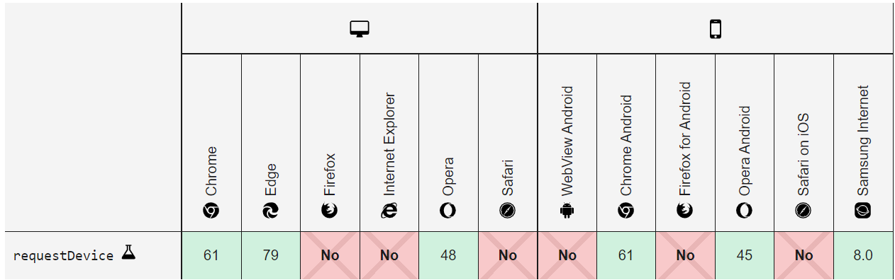
2.6 SWS

Before setting the single wire synchronization speed, make sure the project meets below conditions:

1) The power supply is normal. 2) The MCU is not in "low power" mode. 3) The MCU's single wire function is available. 4) The system clock is normal.

When the connection between "Burning EVK" and the target board cannot be established, the user can try to set the synchronization speed of Swire to establish the connection. Note: The Swire register address may vary depending on the chip type. The four editable boxes in front of the "SWS" button allow you to change the speed of the "Burning EVK" and the target board, click the "SWS" button to perform Swire synchronization. It is recommended to perform a Swire sync to check if the communication with the target board is normal before downloading the firmware to the target board or debugging the MCU. If the communication status with the target board is wrong, you can solve the problem according to the method mentioned in the beginning of Section 2.6. The following figure shows the demonstration when the synchronization is successful.

2.7 Multi-address download

Select the chip model corresponding to the target board, open the "Multi Addr Download" tab, enter the first address of the download in the input box, click the button in the left column to select the local file, the file name displayed in the right column varies according to the selected chip, the file on the right side is stored on the server end. You can do multiple selections for the local file and the server-end file for multi-address downloading. The figure of using the multi-address download function is as follows.

2.8 Firmware upgrade

There are two types of firmware upgrade, one is to select the local firmware to update "Burning EVK", and the other is to click the Firmware drop-down box under the "Online" tab to select the corresponding firmware version number, then the firmware will be downloaded from the server end to update. The firmware update function is demonstrated in the following figure.

2.9 File upload

Open the "Online" tab, fill in the LinkCode input box with the correct one-time connection code, click the "Upload File" button, select the local file to be uploaded, and enter the relative directory name saved in the server in the Directory input box. The file upload function is demonstrated in the following figures.

3. Standalone WEB BDT

Download   Off-line for Windows    Install USB driver   Driver for WEB BDT   and update the latest "Burning EVK" firmware   Firmware for Burning EVK    Click "Start.vbs" and "Close.vbs" to start or close the program.

4、Windows for BDT

Download: Windows for BDT   the user guide is included in the downloaded file.