

The TLSR8258F512 integrates a powerful 32-bit MCU developed by Telink. The digital core is based on 32-bit RISC, and the length of instruction is 16 bits;
The TLSR8258F512 supports six working modes, including Active, Idle, Suspend, Deepsleep with SRAM Retention, Deepsleep without SRAM retention, and Shutdown.
The chip supports 4 types of reset methods, including Power-On Reset, Pin Reset, Watchdog Reset and Software Reset.
| Bit | Modules | Description |
|---|---|---|
| 0 | SPI | reset SPI module |
| 1 | I2C | reset I2C module |
| 2 | UART | reset UART module |
| 3 | USB | reset USB module |
| 4 | PWM | reset PWM module |
| 5 | QDEC | reset QDEC module |
| 7 | Swire | reset Swire module |
| 8 | ZB | reset ZB module |
| 9 | System Timer | reset System Timer module |
| 10 | DMA | reset DMA module |
| 11 | ALGM | reset ALGM module |
| 12 | AES | reset AES module |
| 13 | ADC | reset ADC module |
| 14 | ALG | reset ALG module |
| 16 | AIF | reset AIF module |
| 17 | Audio | reset Audio module |
| 18 | DFIFO | reset DFIFO module |
| 20 | RISC | reset RISC module |
| 21 | MCIC | reset MCIC module |
| 22 | RISC(R) | reset RISC(R) module |
| 23 | MCIC(R) | reset MCIC(R) module |
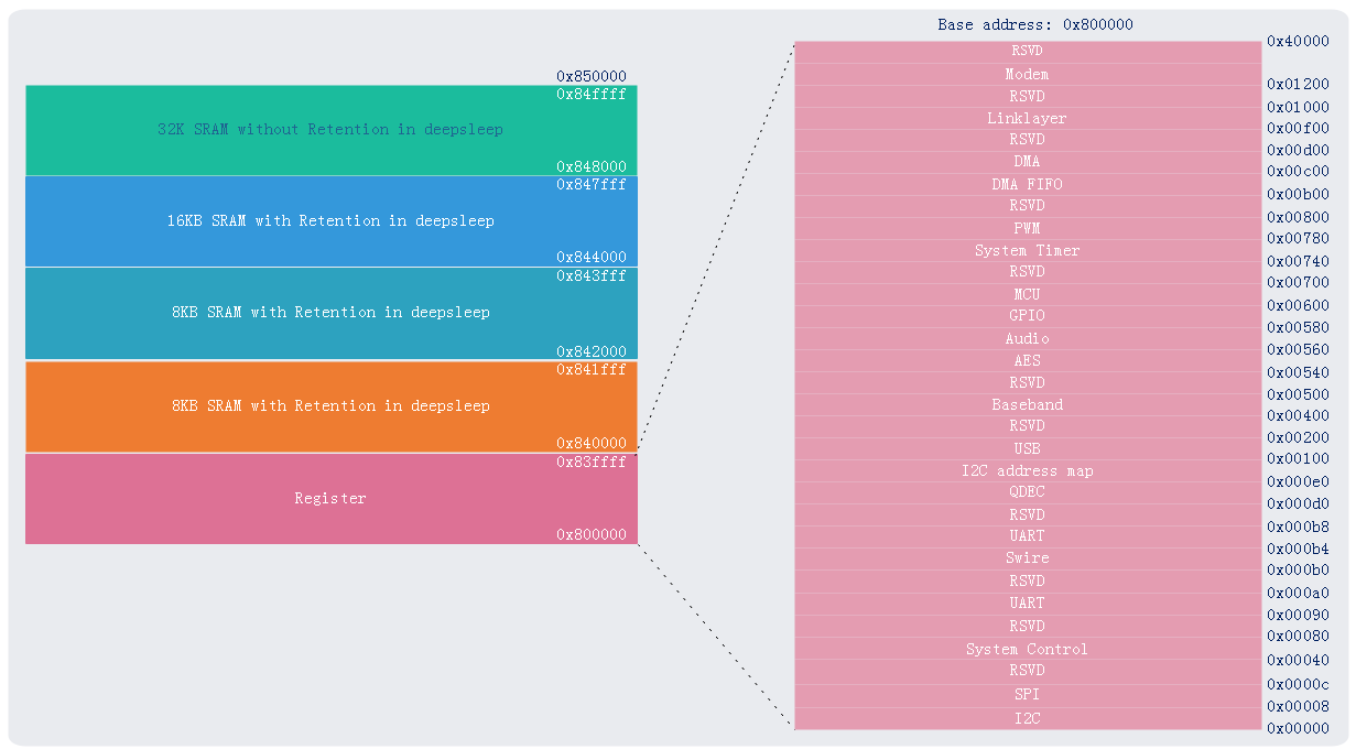
The TLSR8258F512 embeds 64KB SRAM (including one 32KB SRAMs with retention in deepsleep and one 32KB SRAMs without retention in deepsleep) as data memory, and 512KB internal FLASH as program memory.
SRAM and Register memory map is shown as follows. Register can be roughly divided into two parts, which includes Analog register and Digital register. digital register and SRAM can be accessed directly by instruction, while Analog register can only be accessed through the specified API.
The internal Flash mainly supports page program, sector/block/chip erase operations, and deep power down operation. for more detail ...
For chip identification and traceability, the Flash is preloaded with Unique ID (UID). User is not allowed to modify this preloaded UID, But can read the UID via corresponding API interface.
The non-volatile E-Fuse section is preloaded with 4-byte decryption key and 4-byte chip UID, as shown below
| E-Fuse Bit Information | Decryption | Chip UID | |||||
|---|---|---|---|---|---|---|---|
| Coordinate X | Coordinate Y | Wafer NO. | Lot NO. | Internal information | Lot No. | ||
| Bit0 ~ Bit31 | Bit32 ~ Bit39 | Bit40 ~ Bit47 | Bit48 ~ Bit52 | Bit53 ~ Bit55 | Bit56 ~ Bit62 | Bit63 | |
The TLSR8258F512 supports multiple firmware encryption methods to achieve the anti-cloning protection, including:
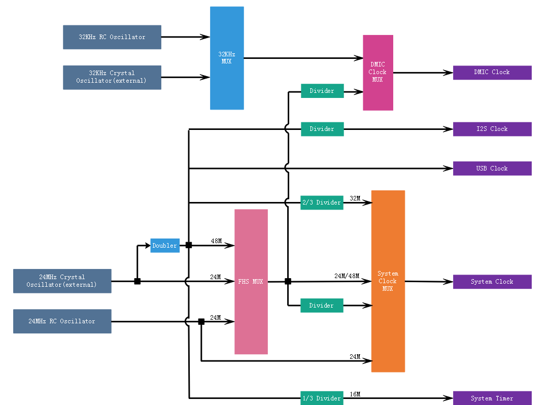
The TLSR8258F512 embeds a 24MHz RC oscillator which can be used as clock source for system, as well as a 32KHz RC oscillator to provide clock source for DMIC and work as wakeup source in suspend or deepsleep mode.
External 24MHz crystal is available via pin XC1 and XC2, which can provide a Pad_24MHz clock source for system and system timer, and generate a 48M clock via a frequency doubler to provide clock source for system, I2S and USB.
External 32K crystal is available via pin PC<2:3>, which can provide a 32KHz clock source for DMIC and work as wakeup source in suspend or deepsleep mode.
The TLSR8258F512 support 4 selectable system clock sources as follows:
User can enable or disable clock for various modules by the relative API functions. By disable the clocks of unused modules, current consumption could be reduced.
The specific description of the clock source of each module is shown in the following table.
| Module Name | Clock Source | Description |
|---|---|---|
| System Timer | external 24MHz crystal | The clock frequency is fixed as 16MHz via a 2/3 frequency divider |
| ADC | external 24MHz crystal | 24M/(1+Divider) |
| Audio | DMIC: external 32K crystal or 32KHz RC | 32K from 32KHz crystal or 32KHz RC |
| DMIC: external 24MHz crystal | a 48M clock via a frequency doubler | |
| I2S: external 24MHz crystal | 48M*I2S_step/I2S_mode | |
| Flash | System Clock | System Clock/(2*Divider) |
| I2C | System Clock | System Clock/(4*Divider) |
| PM | 32K Clock | external 32K crystal or internal 32K RC |
| PWM | System Clock | System Clock/(1+Divider) |
| QDEC | 32K Clock | external 32K crystal or internal 32K RC |
| RF | external 24MHz crystal | external 24MHz crystal |
| 7816 | System Clock | System Clock/(2*Divider) |
| SPI | System Clock | System Clock/(2*(Divider+1)) |
| Timer | System Clock | all modes of Timer works based on System Clock |
| UART | System Clock | Baudrate of UART is set based on System Clock |
| USB | external 24MHz crystal | a 48M clock via a frequency doubler |
The interrupting function is applied to manage dynamic program sequencing based on real-time events triggered by timers, pins and so on. In this chip, all interrupt sources are supported as follows:
| No. | Trigger Type | Interrupt Source | Decription |
|---|---|---|---|
| 1 | Level Trigger | Timer0 | interrupt is triggered by Timer0 |
| 2 | Timer1 | interrupt is triggered by Timer1 | |
| 3 | Timer2 | interrupt is triggered by Timer2 | |
| 4 | USB:Power-down | interrupt is triggered when receiving Power-down signal from USB host | |
| 5 | DMA | interrupt is triggered when data process is finished in DMA | |
| 6 | DFIFO | interrupt is triggered when data process is finished in DFIFO | |
| 7 | UART | interrupt is triggered when data process is finished in UART | |
| 8 | MIX:QDEC/I2C/SPI | interrupt is triggered when data process is finished in QDEC/I2C/SPI | |
| 9 | USB:SETUP | interrupt is triggered when receiving SETUP signal from USB host | |
| 10 | USB:DATA | interrupt is triggered when receiving DATA signal from USB host | |
| 11 | USB:STATUS | interrupt is triggered when receiving STATUS signal from USB host | |
| 12 | USB:SETINF | interrupt is triggered when receiving SETINF signal from USB host | |
| 13 | USB:EndPoint | interrupt is triggered when data process is finished in USB EndPoint | |
| 14 | ZB_RT:Baseband | interrupt is triggered when data process is finished in ZB_RT | |
| 15 | PWM | interrupt is triggered when data process is finished in PWM | |
| 16 | Edge Trigger | USB:250us | interrupt is triggered when USB in Idle for 250us |
| 17 | USB:reset | interrupt is triggered when receiving RESET command from USB host | |
| 18 | GPIO | interrupt is triggered in the rising or falling edge of GPIO | |
| 19 | PM:32k timer | interrupt is triggered after waking up MCU in deepsleep or suspend mode by 32k timer | |
| 20 | system timer | interrupt is triggered when the tick value of System timer and the specified capture value matches | |
| 21 | GPIO2RISC_1 | interrupt is triggered in the rising or falling edge | |
| 22 | GPIO2RISC_0 | interrupt is triggered in the rising or falling edge |
If you want to use interrupt function of the certain module, you must set as the following step:
When more than one interrupt sources assert interrupt requests at the same time, MCU will respond depending on respective interrupt priority levels. But this chip only supports a level-2 priority, which means that When the concurrent situation occurs, only the interrupt with high priority is received, and other interrupt signals are all blocked.
In order to facilitate users to quickly develop products according to their own needs, TSI provide the following related APIs and examples.
| APIs list | Description | Example | Update Date | Status |
|---|---|---|---|---|
| start_reboot() | reset the whole chip | API-CORE-CASE1 | 2019-1-10 | Done |
| analog_read() | read one byte from analog register | API-CORE-CASE1 | 2019-1-10 | Done |
| analog_write() | write one byte into analog register | API-CORE-CASE1 | 2019-1-10 | Done |
| READ_REG8() | read one byte from analog register | refer to API-CORE-CASE1 | 2019-1-10 | Done |
| WRITE_REG8() | write one byte into analog register | refer to API-CORE-CASE1 | 2019-1-10 | Done |
| READ_REG16() | read one byte from analog register | refer to API-CORE-CASE1 | 2019-1-10 | Done |
| WRITE_REG16() | write one byte into analog register | refer to API-CORE-CASE1 | 2019-1-10 | Done |
| READ_REG32() | read one byte from analog register | API-CORE-CASE1 | 2019-1-10 | Done |
| WRITE_REG32() | write one byte into analog register | API-CORE-CASE1 | 2019-1-10 | Done |
| cpu_wakeup_init() | initialize MCU for running | API-CORE-CASE1 | 2019-1-10 | Done |
| clock_init() | set system clock for MCU, system clock is 24M RC by default | API-CORE-CASE1 | 2019-1-10 | Done |
| clock_32k_init() | set 32K clock for MCU, 32K clock is 32K RC by default | - | 2019-1-10 | Done |
| rc_24m_cal() | calibrate the RC1 to 24M as system clock | API-CORE-CASE2 | 2019-1-10 | Done |
| rc_48m_cal() | calibrate the RC1 to 48M as system clock | - | 2019-1-10 | Done |
| rc_32k_cal() | calibrate the RC2 to 32K as 32k timer | API-CORE-CASE2 | 2019-1-10 | Done |
| doubler_calibration() | calibrate the doubler | API-CORE-CASE2 | 2019-1-10 | Done |
APIs related to interrupt are listed below.
| APIs list | Description | Example | Update Date | Status |
|---|---|---|---|---|
| irq_handler() | all interrupt signal will be captured and handled in this function | - | 2019-1-10 | Done |
| irq_enable() | enable global interrupt | API-RF-CASE25 | 2019-1-10 | Done |
| irq_disable() | disable global interrupt and return the current interrupt settings | API-RF-CASE25 | 2019-1-10 | Done |
| irq_restore() | restore global interrupt | - | 2019-1-10 | Done |
| irq_enable_type() | set interrupt mask | API-RF-CASE25 | 2019-1-10 | Done |
| irq_get_mask() | get interrupt mask | - | 2019-1-10 | Done |
| irq_disable_type() | clear the specified interrupt mask | 2019-1-10 | Done | |
| irq_get_src() | get the interrupt source | - | 2019-1-10 | Done |
| irq_clr_src2() | clear the specified interrupt source | - | 2019-1-10 | Done |
| irq_clr_src() | clear all interrupt source | API-RF-CASE25 | 2019-1-10 | Done |
| rf_irq_enable() | set RF interrupt mask | API-RF-CASE25 | 2019-1-10 | Done |
| rf_irq_disable() | clear the specified RF interrupt mask | API-RF-CASE25 | 2019-1-10 | Done |
| rf_irq_src_get() | get the RF interrupt source | - | 2019-1-10 | Done |
| rf_irq_clr_src() | clear the specified interrupt source | - | 2019-1-10 | Done |
TSI provides the following examples of this module to help users quickly understand and apply related modules.
| Examples list | Description | Update Date | Status |
|---|---|---|---|
| API-CORE-CASE1 | access memory including digital register, analog register and SRAM | 2019-1-10 | Done |
| API-CORE-CASE2 | calibrate the 24M RC, 32K RC and doubler | 2019-1-10 | Done |
| API-IRQ-CASE1 | interrupt signal of Timer0 will be captured and handled in this case | 2019-1-10 | Done |
| API-IRQ-CASE2 | interrupt signal of Timer1 will be captured and handled in this case | 2019-1-10 | Done |
| API-IRQ-CASE3 | interrupt signal of Timer2 will be captured and handled in this case | 2019-1-10 | Done |
| API-IRQ-CASE4 | interrupt signal of USB Power down will be captured and handled in this case | 2019-1-10 | Todo |
| API-IRQ-CASE5 | interrupt signal of DMA will be captured and handled in this case | 2019-1-10 | Done |
| API-IRQ-CASE6 | interrupt signal of DFIFO will be captured and handled in this case | 2019-1-10 | Todo |
| API-IRQ-CASE7 | interrupt signal of UART will be captured and handled in this case | 2019-1-10 | Done |
| API-IRQ-CASE8 | interrupt signal of MIX(QDEC, I2C and SPI) will be captured and handled in this case | 2019-1-10 | Done |
| API-IRQ-CASE9 | interrupt signal of USB SETUP will be captured and handled in this case | 2019-1-10 | Todo |
| API-IRQ-CASE10 | interrupt signal of USB DATA will be captured and handled in this case | 2019-1-10 | Todo |
| API-IRQ-CASE11 | interrupt signal of USB STATUS will be captured and handled in this case | 2019-1-10 | Todo |
| API-IRQ-CASE12 | interrupt signal of USB SETINF will be captured and handled in this case | 2019-1-10 | Todo |
| API-IRQ-CASE13 | interrupt signal of USB EndPoint will be captured and handled in this case | 2019-1-10 | Todo |
| API-IRQ-CASE14 | interrupt signal of ZB_RT(Baseband) will be captured and handled in this case | 2019-1-10 | Done |
| API-IRQ-CASE15 | interrupt signal of PWM will be captured and handled in this case | 2019-1-10 | Done |
| API-IRQ-CASE16 | interrupt signal of USB 250us will be captured and handled in this case | 2019-1-10 | Todo |
| API-IRQ-CASE17 | interrupt signal of USB RESET will be captured and handled in this case | 2019-1-10 | Todo |
| API-IRQ-CASE18 | interrupt signal of GPIO will be captured and handled in this case | 2019-1-10 | Done |
| API-IRQ-CASE19 | interrupt signal of PM(32K Timer) will be captured and handled in this case | 2019-1-10 | Todo |
| API-IRQ-CASE20 | interrupt signal of System Timer will be captured and handled in this case | 2019-1-10 | Todo |
| API-IRQ-CASE21 | interrupt signal of GPIO2RISC_1 will be captured and handled in this case | 2019-1-10 | Done |
| API-IRQ-CASE22 | interrupt signal of GPIO2RISC_0 will be captured and handled in this case | 2019-1-10 | Done |
| Date | Description | Author |
|---|---|---|
| 2019-1-10 | initial release | LJW |
| 2019-8-15 | update api name for application | LJW |