

The TLSR 8258F512 embeds one quadrature decoder(QDEC) which is designed mainly for applications such as wheel. The QDEC implements debounce function to filter out jitter on the two phase inputs, and generates smooth square waves for the two phase.
The QDEC supports two phase input. Each input is selectable from the 8 pins of PortD, PortC, PortB and PortA via setting reg_qdec_channel_a and reg_qdec_channel_b.
| Pin | reg_qdec_channel_a | reg_qdec_channel_b |
|---|---|---|
| A2 | 0 | 0 |
| A3 | 1 | 1 |
| B6 | 2 | 2 |
| B7 | 3 | 3 |
| C2 | 4 | 4 |
| C3 | 5 | 5 |
| D6 | 6 | 6 |
| D7 | 7 | 7 |
But this choice is not free, for example, A2 and A3 are a fixed group, B6 and B7 are a fixed group. more details are as follows:
| Port | reg_qdec_channel_a | reg_qdec_channel_b |
|---|---|---|
| Port A | A2 | A3 |
| Port B | B6 | B7 |
| Port C | C2 | C3 |
| Port D | D6 | D7 |
Note: To use corresponding IO as QDEC input pin, it's needed first to enable GPIO function, enable input and disable output by API function
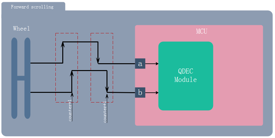
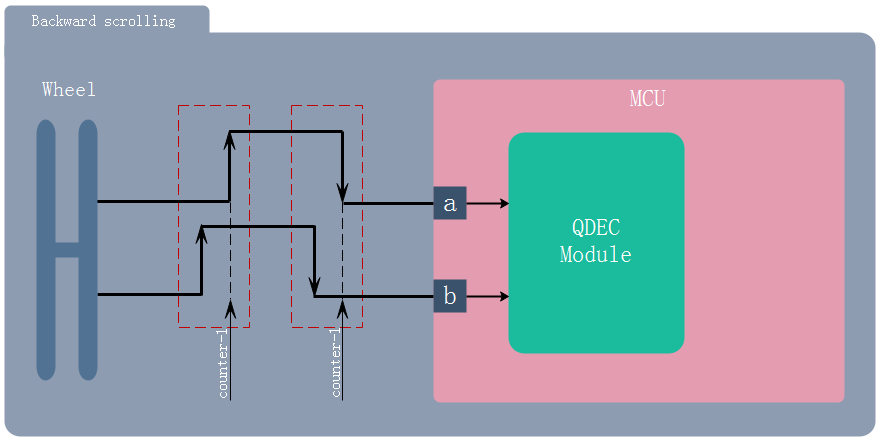
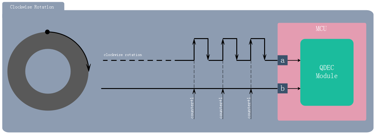
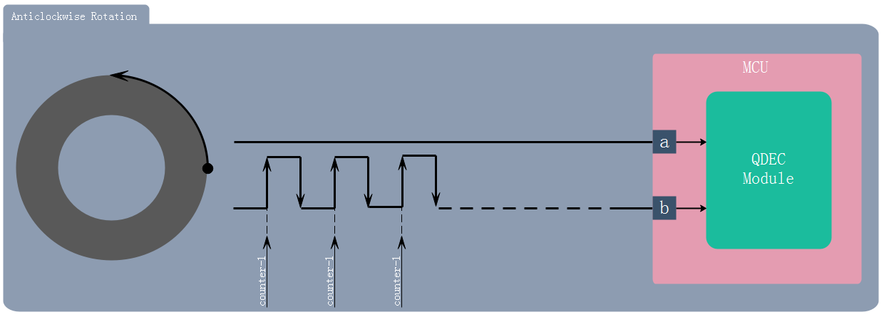
For each wheel rolling step, two pulse edges(rising edge or falling edge) are generated. In Common Mode, only when the same rising or falling edges are detected from the two phase signals, the QDEC Counter value(real time counting value)is increased or decreased by 1.
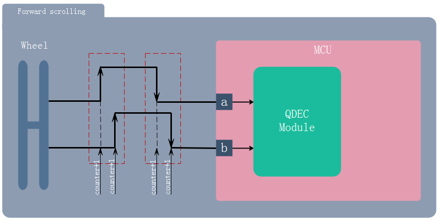
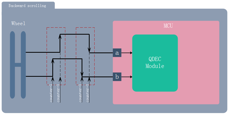
In Double Accuracy Mode, the QDEC Counter value(real time counting value) is increased or decreased by 1 when each rising edge or falling edge is generated. In other words, one wheel rolling step will generate 4 edges including 2 rising edges and 2 falling edges, which means that counter will increase or decrease by 4
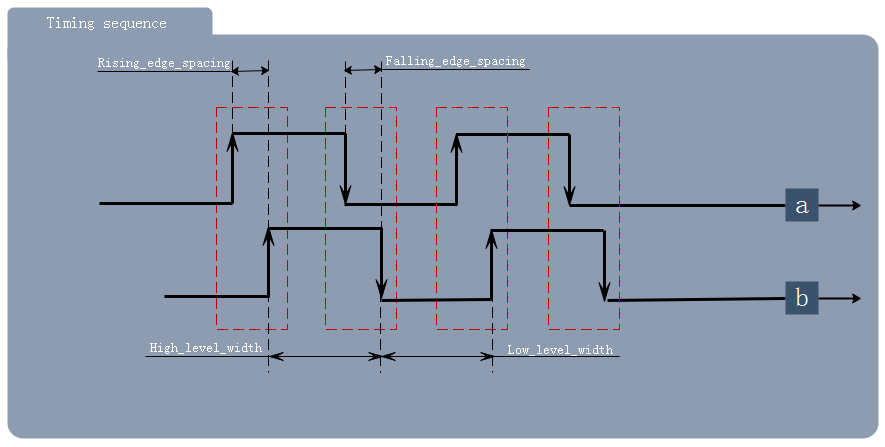
The QDEC supports hardware debouncing. All jitter with period less than the specified value will be filtered out and thus do not trigger counter change. QDEC module works based on 32KHz clock to ensure it can work in suspend mode. The 2^n * clk_32KHz ( n is set by API function)clock is used to synchronize input signal of QDEC module, so Rising_edge_spacing and Falling_edge_spacing should exceed 2^n * clk_32KHz as the following chart. Therefore, High_level_width and Low_level_width must be not less than 2^n * clk_32KHz clock * 3 to ensure that counter works normally.
In normal (NOT shuttle) mode, non-overlapping two phase signals is not permitted, which means that counter will not change when non-overlapping two phase signals generates. Shuttle Mode allows non-overlapping two phase signals as follows. The application of this mode is usually shown in household appliances.
In order to facilitate users to quickly develop products according to their own needs, TSI provide the following related APIs and examples.
| APIs list | Description | Example | Update Date | Status |
|---|---|---|---|---|
| qdec_set_pin() | set pin of QDEC | API-QDEC-CASE1 | 2019-1-10 | Done |
| qdec_set_mode() | set mode of QDEC | API-QDEC-CASE1 | 2019-1-10 | Done |
| qdec_set_debouncing() | set hardware debouncing for QDEC | API-QDEC-CASE1 | 2019-1-10 | Done |
| qdec_clk_en() | enable clock for QDEC | API-QDEC-CASE1 | 2019-1-10 | Done |
| qdec_get_count_value() | get the count value of QDEC | API-QDEC-CASE1 | 2019-1-10 | Done |
| qdec_clear_conuter() | clear counter of QDEC | - | 2019-1-10 | Done |
TSI provides the following examples of this module to help users quickly understand and apply related modules.
| Examples list | Description | Update Date | Status |
|---|---|---|---|
| API-QDEC-CASE1 | QDEC in Common Mode | 2019-1-10 | Todo |
| API-QDEC-CASE2 | QDEC in Double Accuracy Mode | 2019-1-10 | Done |
| API-QDEC-CASE3 | QDEC in Shuttle Mode | 2019-1-10 | Todo |
| Date | Description | Author |
|---|---|---|
| 2019-1-10 | initial release | LJW |