

The TLSR8258F512 embeds SPI(Serial Peripheral Interface), which could act as Master mode or Slave mode. SPI is a high-speed, full-duplex and synchronous communication bus requiring 4 bus lines including a chip select(CS) line, a data input(DI) line,a data output(DO) line and a clock(CK) line.
SPI for the TLSR8258F512 supports both master mode and slave mode, and acts as slave mode by default.
In SPI Master mode, Telink SPI supports four standard working modes: Mode0, Mode1, Mode2 and Mode3, which means that different combinations of clock polarity and clock phase:
SPI Slave mode supports DMA. User could access registers of the TLSR8258F512 by SPI interface. It's noted that system clock of TLSR8258F512 shall be at least 5x faster than SPI clock for reliable connection.
In SPI Slave mode, Receive data at positive edge of SPI MCLK clock and send data at negative edge of SPI MCLK clock.
SPI Slave mode only supports two standard working modes: Mode0 and Mode3.
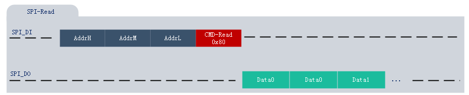
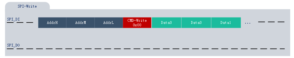
It should be noted that compared to the previous chip series, the starting address of the sram of TLSR8258 starts from 0x840000, which means that if you want to access SRAM of TLSR8258, the length of the access address needs at least up to 3 bytes. Besides, SPI Slave mode also supports address auto increment.
SPI write command format and read command format are illustrated as follows:
SPI hardware and I2C hardware modules in the chip share part of the hardware, as a result, when both hardware interfaces are used, the restrictions listed within this section need to be taken into consideration.
In order to facilitate users to quickly develop products according to their own needs, TSI provide the following related APIs and examples.
| APIs list | Description | Example | Update Date | Status |
|---|---|---|---|---|
| reset_spi_moudle() | reset the module of SPI | - | 2019-1-10 | Done |
| spi_master_gpio_set() | select pins for the SPI interface | API-SPI-CASE1 | 2019-1-10 | Done |
| spi_slave_gpio_set() | select pins for the SPI interface | API-SPI-CASE2 | 2019-1-10 | Done |
| spi_masterCSpin_select() | select pins for the SPI interface | API-SPI-CASE1 | 2019-1-10 | Done |
| spi_master_init() | initiate the master device(SPI clock and SPI mode) | API-SPI-CASE1 | 2019-1-10 | Done |
| spi_slave_init() | initiate the slave device(SPI clock and SPI mode) | API-SPI-CASE2 | 2019-1-10 | Done |
| spi_write() | write a bulk of data to the SPI slave device | API-SPI-CASE1 | 2019-1-10 | Done |
| spi_read() | read a bulk of data from the SPI slave device | API-SPI-CASE1 | 2019-1-10 | Done |
TSI provides the following examples of this module to help users quickly understand and apply related modules.
| Examples list | Description | Update Date | Status |
|---|---|---|---|
| API-SPI-CASE1 | SPI in Master Mode | 2019-1-10 | Done |
| API-SPI-CASE2 | SPI in Slave Mode | 2019-1-10 | Done |
| Date | Description | Author |
|---|---|---|
| 2019-1-10 | initial release | LJW |
| 2019-8-15 | update api name for application | LJW |