

The PWM module of TLSR8258 essentially compares the count value of the built-in counter with the set target count value. If they are the same, the level of the corresponding GPIO port will be reversed. If it is different, the state will remain unchanged.
The TLSR8258F512 supports 6-channel PWM(Pulse-Width-Modulation) output. Each PWM#n(n=0 ~ 5) has its corresponding inverted output at PWM#n_N pin. Refer to GPIO multiplexing function list to see which GPIOs support PWM functions.The clock source of the PWM module is the system clock.
Before describing the PWM mode, it is necessary to have some understanding of some design ideas of PWM. Among them, three very important concepts are waveform of signal frames, Invert PWM Output and Polarity for signal frame.
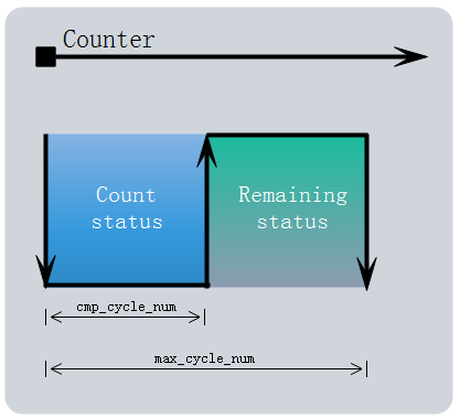
Assume that the level of the PWM is high in the count status. Set the number of cycles for the count status to cmp_cycle_num and set the number of cycles for a signal frame to max_cycle_num. As shown below, The workflow of the PWM module is as follows:

By configuration we can directly invert the output of the PWM, which means that waveform of the corresponding PWM channel will be inverted completely.
The level of the PWM is high in the count status by default, which is configurable by the polarity(default: high). Configuring the polarity to be low and directly flipping the output level is the same effect. In other words, if the level of the PWM is set to low in the count status, waveform of the corresponding PWM channel will be also inverted completely.
PWM module of TLSR8258 support five modes,including:
NOTE:only PWM0 support all modes, while PWM1 ~ PWM5 only support Continuous mode.
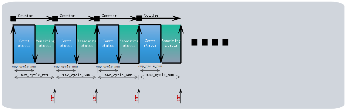
PWM0 ~ PWM5 all support Continuous mode. In this mode, PWM module continuously sends out signal frames till it is stopped by configuration. when stopped, the PWM output will turn low immediately.
During Continuous mode, waveform could be changed freely via configuring cmp_cycle_num and max_cycle_num. New configuration will take effect in the next signal frame.
After each signal frame is finished, a frame interruption will be generated if the relevant interrupt configuration is turned on. for more detail ...
Only PWM0 supports Counting mode. In this mode, the number of signal frames PWM0 sends out can be defined.
After each signal frame is finished, a frame interruption will be generated. for more detail ...
Multiple signal frames can form a pulse group, after a pulse group is finished, PWM0 will be disabled auto maitically, and a pulse group interruption will be generated if the relevant interrupt configuration is turned on. for more detail ...

Only PWM0 supports IR mode. In this mode, specified number of signal frames is defined as one pulse group. In contrast to Counting mode where PWM0 stops after first pulse group is finished, PWM0 will constantly send pulse groups in IR mode.
During IR mode, PWM0 output waveform could also be changed freely via configurating cmp_cycle_num , max_cycle_num and pulse_group_num. New configuration will take effect in the next pulse group.
To stop IR mode after completing current pulse group, user can switch PWM0 from IR mode to Counting mode so that PWM0 will completely send out current pulse group. If PWM0 is disabled, PWM0 output will turn Low immediately despite of current pulse group.

Only PWM0 support IR FIFO mode. IR FIFO mode is designed to allow IR transmission of long code patterns without the continued intervention of MCU, and it is designed as a selectable working mode on PWM0. The IR carrier frequency is divided down from the system clock and can be configured as any normal IR frequencies, e.g. 36KHz,38KHz,40KHz,56KHz.
IR FIFO Mode define an element written into FIFO as basic unit of IR waveform. This element consists of 16bits, defined as follows: {#ELEM}
The element is written into FIFO by 4-byte register. About FIFO, the description is as follows:
Only PWM0 support IR DMA FIFO mode. This mode is similar to IR FIFO mode, except that the element is written into FIFO by DMA instead of MCU. User should configure the relative parameter for DMA, and then DMA will automatically write the configuration into FIFO. When DMA channel 5 is enabled, PWM will automatically output configured waveform, for more detail...
After all waveforms are sent, FIFO becomes empty. PWM0 will be disabled automatically.
In order to facilitate users to quickly develop products according to their own needs, TSI provide the following related APIs and examples.
| APIs list | Description | Example | Update Date | Status |
|---|---|---|---|---|
| pwm_set_mode() | set the mode of PWM#n | API-PWM-CASE1 | 2019-1-10 | Done |
| pwm_set_clk() | set the clock of PWM module | API-PWM-CASE1 | 2019-1-10 | Done |
| pwm_set_cycle_and_duty() | set the max_cycle_num and cmp_cycle_num of PWM#n | API-PWM-CASE1 | 2019-1-10 | Done |
| pwm_set_pwm0_shadow_cycle_and_duty() | set the shadow max_cycle_num and cmp_cycle_num of PWM | API-PWM-CASE3 | 2019-1-10 | Done |
| pwm_set_pulse_num() | set pulse_group_num of PWM#n | API-PWM-CASE1 | 2019-1-10 | Done |
| pwm_start() | start PWM#n | API-PWM-CASE1 | 2019-1-10 | Done |
| pwm_stop() | stop PWM#n | - | 2019-1-10 | Done |
| pwm_revert() | revert output of PWM#n | - | 2019-1-10 | Done |
| pwm_n_revert() | revert output of PWM_n_#n | - | 2019-1-10 | Done |
| pwm_polo_enable() | set the polarity of PWM#n | - | 2019-1-10 | Done |
| pwm_config_dma_fifo_waveform() | set the carrier of PWM#n in IR DMA FIFO Mode | API-PWM-CASE5 | 2019-1-10 | Done |
| pwm_set_dma_address() | set the address for DMA | API-PWM-CASE5 | 2019-1-10 | Done |
| pwm_start_dma_ir_sending() | start PWM0 in IR DMA FIFO mode to send data | API-PWM-CASE5 | 2019-1-10 | Done |
| pwm_stop_dma_ir_sending() | stop PWM0 in IR DMA FIFO mode to send data | API-PWM-CASE5 | 2019-1-10 | Done |
TSI provides the following examples of this module to help users quickly understand and apply related modules.
| Examples list | Description | Update Date | Status |
|---|---|---|---|
| API-PWM-CASE1 | PWM in Continuous Mode | 2019-1-10 | Done |
| API-PWM-CASE2 | PWM in Counting Mode | 2019-1-10 | Done |
| API-PWM-CASE3 | PWM in IR Mode | 2019-1-10 | Done |
| API-PWM-CASE4 | PWM in IR FIFO Mode | 2019-1-10 | Done |
| API-PWM-CASE5 | PWM in IR DMA FIFO Mode | 2019-1-10 | Done |
| Date | Description | Author |
|---|---|---|
| 2019-1-10 | initial release | LJW |
| 2019-8-15 | update api name for application | LJW |