B85 Mesh Starter Kit Hardware Guide
Contents
Introduction
The guide introduces how to get started with the B85 Mesh Starter Kit. The Kite Mesh Starter Kit is a hardware platform based on TLSR8258, which can be used to verify the TLSR825x series chipset and develop applications for multiple 2.4GHz wireless networks including Bluetooth® Mesh and Zigbee 3.0.
Material List
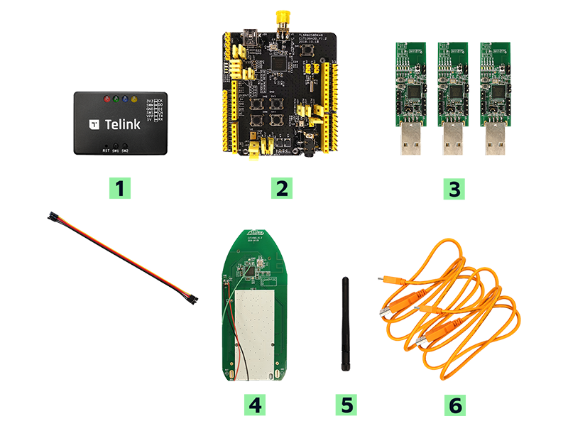
| Item | S/N | Product Name | Qty |
|---|---|---|---|
| 1 | TLSRGSOCBK56B | Telink Burning Board (SWS BURING EVK, including DuPont wires) | 1 |
| 2 | TLSR8258DK48D | TLSR8258 Development Board | 1 |
| 3 | TLSR8258DG48D | TLSR8258 Dongle | 3 |
| 4 | TLSR8258MRC32D | TLSR8258 Mesh RCU | 1 |
| 5 | Whip antenna | 2.4Ghz antenna | 1 |
| 6 | USB cable | USB A to mini USB | 2 |
The B85 Mesh Starter Kit includes:
- Multiple USB dongles for simulating mesh nodes or gateways
- Remote control PCBA for simulating remote controller, wall switch, and also for demonstrating group controls
- Telink Burning Board
PC installed with
- TELINK BDT tool
- SIG Mesh Tool for controlling mesh nodes (included in the SIG Mesh SDK.zip, \tools)
Mobile installed with
- Reference Android or iOS APPs (included in the SIG Mesh SDK.zip, \app)
Bluetooth® Mesh Demo
Features
Bluetooth® Mesh demo is presented in 4 different ways:
- Node Control by APP with OTA
- Node Control by Gateway with OTA
- Node Control by Remote
- Node Control by Master Dongle with OTA
Configuring the Starter Kit
You can use the prebuilt binary for the following demo testing - Demo binary based on SDK
- 82xx_mesh.bin - the mesh light node
- 82xx_mesh_gw.bin - the mesh gateway with PB_ADV capability
- 82xx_mesh_LPN.bin - the mesh low power node
- 82xx_mesh_switch.bin - the mesh light switch node
- sig_mesh_master_dongle_8267_69.bin - the mesh master dongle with PB_GATT
For further info, please refer to the Developer Handbook for Telink Bluetooth Mesh SDK.
Node Control by APP
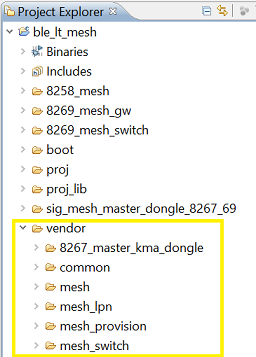
Node control by gateway demo requires 2 pieces of dongle simulating light bulb. They can be either 8258 or 8269. 8258 is used in this example. Light bulb bin is generated by “mesh” project with “8258_mesh” compile option. Available projects in SIG mesh SDK is shown below. The light bulbs, if has been provisioned previously, need to reset by having 3 short power cycling (on/off each 1s) followed by 2 long power cycling (on/off each 3-5s).
Launch “TelinkSigMesh” APP under either Android or IOS. On front page as shown below, click “+” on upper right corner to add device. In “Device Scan” page, scan and wait each node from “binding” to “bound”.
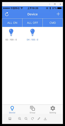
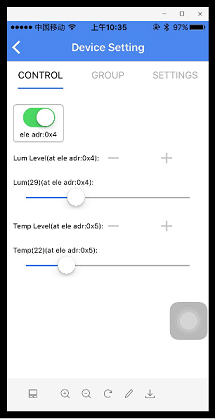
Back to front page, tap on light icon would toggle on/off, long press would enter into “Device Setting” page as shown below. LUM and TEMP level and group assignment can be set in “Control” and “Group” tab, respectively.
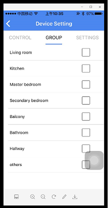
In “SETTINGS” tab as shown below, schedule, subscription, publish model can be set. Device OTA is also enabled. For schedule, macro “MD_TIME_EN” in mesh_config.h under vendor/common/ dir in SDK. Last, “KICK OUT” tab at the bottom would remove the light bulb from network.

Node Control by Gateway
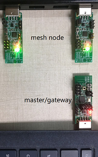
Node control by gateway demo requires 3 pieces of HW as shown below: 2 pieces of light bulb and 1 piece of gateway dongle. In this example, light bulb uses 8258 while gateway dongle is 8269.
8269 dongle in this example is programmed by using “mesh_provision” project in SDK and “8269_mesh_gw(provisioner)” compile option; and light bulb bin is generated by “mesh” project with “8258_mesh” compile option. After being programmed, gateway dongle must be plugged in USB port of PC and light bulbs can be powered by any USB port.
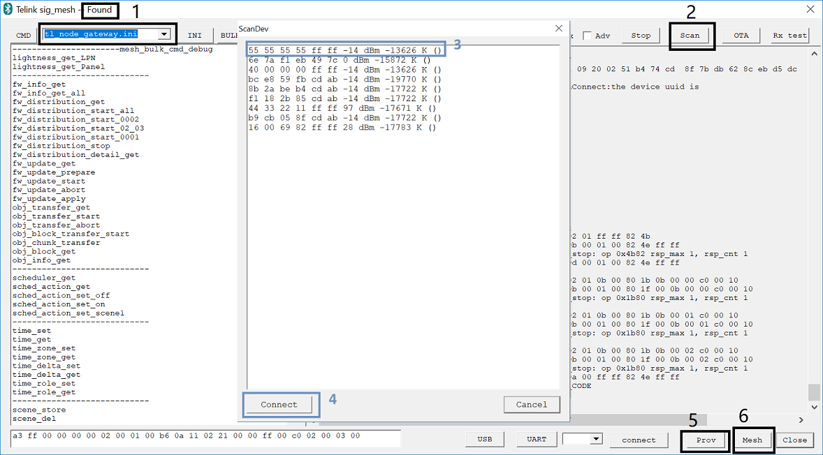
In “sig_mesh_tool”, INI file needs to switch to “tl_node_gateway.ini” in pull down menu as shown below. The light bulbs, if has been provisioned previously, need to reset by having 3 short power cycling (on/off each 1s) followed by 2 long power cycling (on/off each 3-5s). Successful reset would trigger 3 blinks.
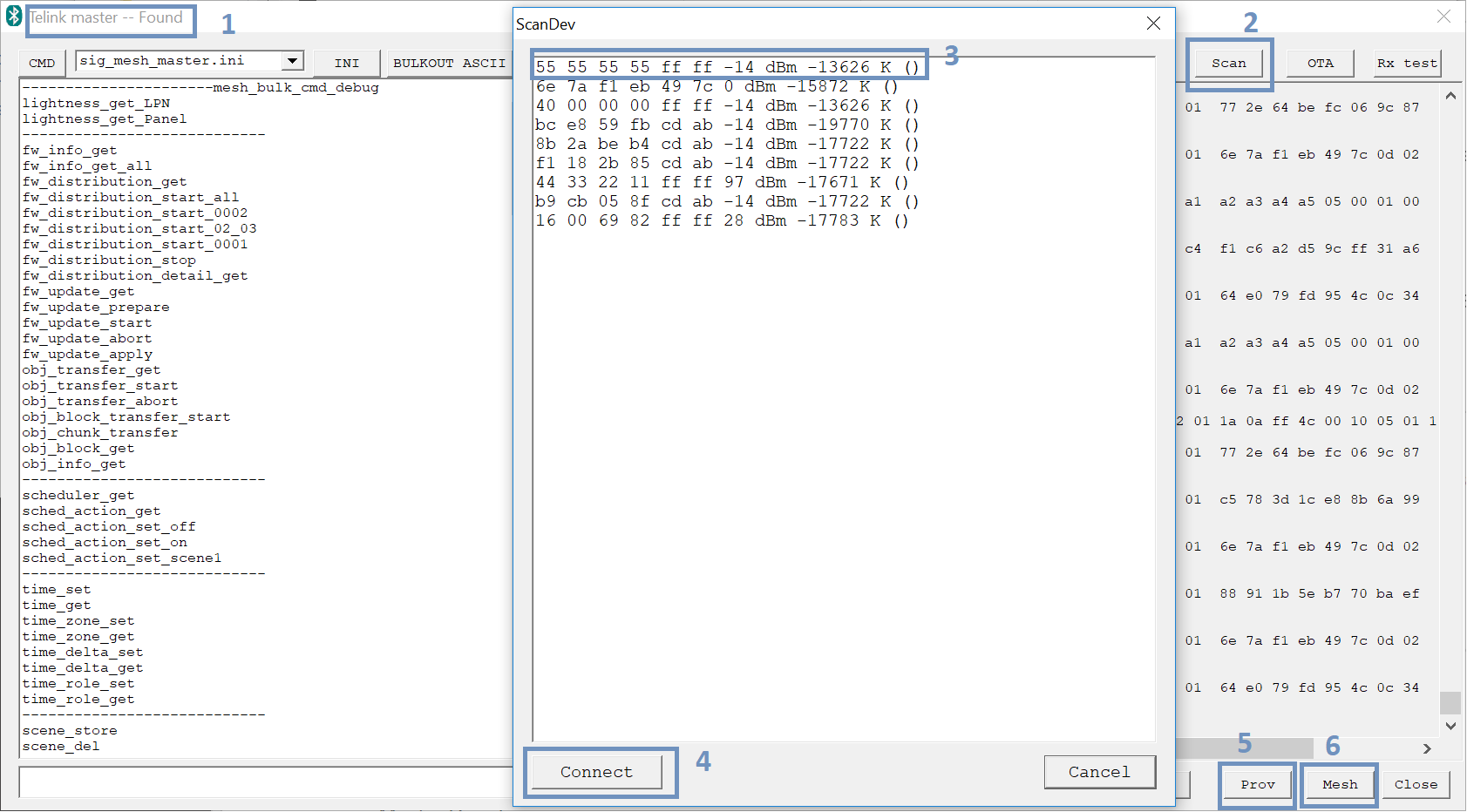
Next step is to launch “sig_mesh_tool” as shown below. Step 1 is to confirm gateway dongle is “Found”. Step 2 is to click on “Scan” button to pop out a window, select the MAC Address of the light bulb as Step 3 and then select “connect” as Step 4. Then click on “Prov” as Step 5. MAC address can be customized using BDT tool.
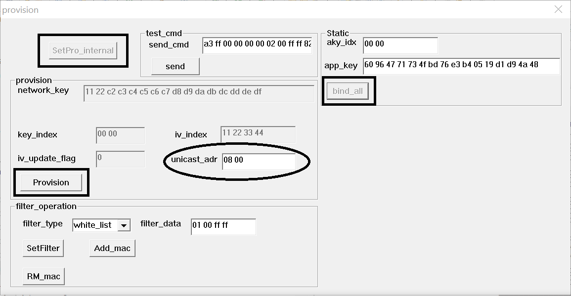
In Provision window as shown below, First click on “setPro_internal” (only once),then “Provision” button on left pane, once provision is finished, “bind_all” on right pane becomes selectable, go ahead select “bind_all” to complete provision. LED on light dongle should blink at provision completion. “Uncast_addr” is automatically incremented by “0x0200” as an unique ID to each light bulb. Repeat “Scan”, “Connect” and “Prov” for the other light bulb.
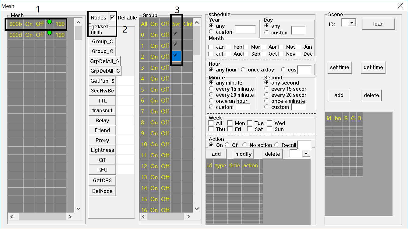
Now continue into Step 6 by clicking on “Mesh” button in “sig_mesh_tool” UI. This will bring out the light control UI as shown below. Light bulbs is listed in the “Mesh” pane on left side of the window with corresponding unicast address. By double clicking on the specific light, as indicated in field “2”, this particular light can be assigned to desired group by checking on the open box as step “3”. Once group assignment is done, each group can be turned off/on by itself.
Node Control by Remote
Following is a lighting remote control HW, SOC can be either 8258 or 8269.
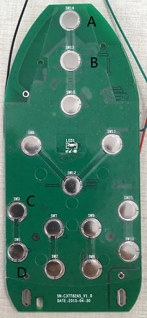
First, generate remote bin file by using “mesh_switch” project in SDK and using “8269_mesh_switch” compile option in this example. Please notice that a button need to be pressed while download FW. Once programmed, the remote control will need to go through the same “scan”, “connect” and “provision” procedure as described above for lighting bulbs. Afterwards, user can use button A and B as indicated to turn all on and all off, respectively, and they are SIG model commands. Press A and D simultaneously will put it in advertising mode, LED will also blink. C and D are to control group on/off, and they are vendor model command, for the time being, only internal printing message are available for C and D commands.
Node Control by Master Dongle
Master dongle demo shares same HW as gateway demo.
Master dongle bin is generated by “8267_master_kma_dongle” project in SDK with compile option “sig_mesh_master_dongle_8267_8269”; and light bulb bin is generated by “8258_mesh” project with “8258 mesh” compile option. After being programmed, master dongle should plug in PC USB port.
In “sig_mesh_tool” as shown below, “sig_mesh_master.ini” is used. Provision and grouping in Mesh window is the same as gateway.
Mesh OTA by Master Dongle
Continuing with the Master Dongle setup, place the new bin file under the same dir as where “sig_mesh_tool” resides, and name it as “new_firmware_tx.bin”. Confirm the mesh nodes status by going into Mesh window and click “Nodes” button.
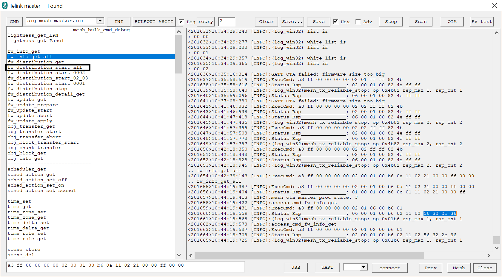
In following window, double click “fw_info_get_all” command, in this example, current version is highlighted in hex “56 32 2e 36” for ASCII V2.6. Continue double click “fw_distribution_start_all” would trigger mesh OTA.
Online Purchase
* The B85 Mesh Starter Kit can be purchased online via Mouser or Taobao.
* Other Development Kits can also be obtained by contacting Telink.