B91 Generic Starter Kit Hardware Guide
Contents
- Introduction
- Material List
- Overview
- Quick Start
- Bluetooth® Mesh + Local Voice Recognition Demo
- Online Purchase
Introduction
The guide introduces how to get started with the B91 Kit. The B91 Generic Starter Kit is a hardware platform which can be used to verify the TLSR9x series chipset and develop applications for several 2.4GHz air interface standards including Bluetooth 5.2(Basic data rate (BR), Enhanced data rate (EDR), LE, Indoor positioning and Bluetooth Mesh), Zigbee 3.0, Homekit, 6LoWPAN, Thread and 2.4Ghz proprietary.
Material List
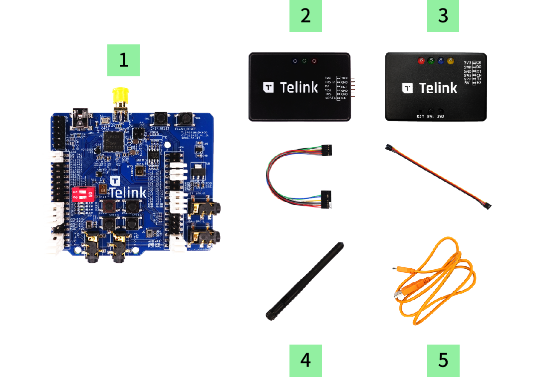
| Item | S/N | Product Name | Qty | Description |
|---|---|---|---|---|
| 1 | TLSR9518ADK80D | B91 Development Board | 1 | including jumpers |
| 2 | TLSRGSOCBK100B | TLSR9 DEV KEY | 1 | JTAG BURING EVK, including DuPont wires |
| 3 | TLSRGSOCBK56B | Telink Burning Board | 1 | SWS BURING EVK, including DuPont wires |
| 4 | Whip Antenna | 1 | 2.4Ghz antenna | |
| 5 | USB cable | 1 | USB A to mini USB |
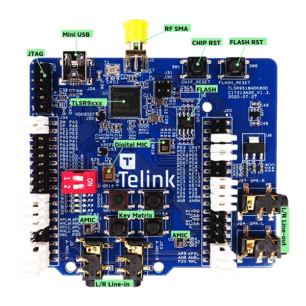
Overview
The pictures below illustrate main components and default jumper setting on TLSR9518ADK80D. The default setting enables the following functionality.
- RF conducted test
- External Flash with reset button
- Chip reset button
- Mini USB interface
- 2-wire / 4-wire JTAG
- 4 led, Key matrix up to 4 keys
- 2 line-in function (Dual Analog microphone supported when switching jumper from microphone path)
- Dual Digital microphone
- Stereo line-out
There are detailed descriptions of jumper setting in the Reference Design.
TLSR9518ADK80D Top View
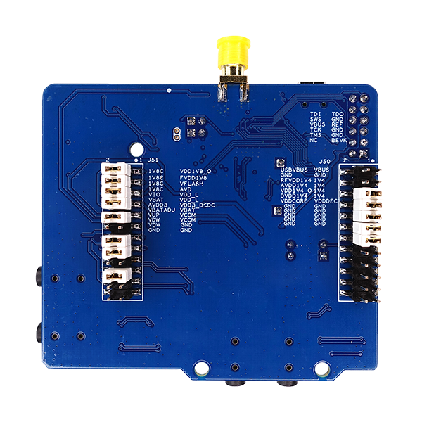
TLSR9518ADK80D Bottom View
Quick Start
Flash Programming
Developers can choose any of the following tools for flash programming.
BQB Test
Click for more details of BQB.
Power Connection Method 1(Default)
Step 1: Connect target board with “Burning EVK” via Swire.
Step 2: Download FW into “FLASH” via “EVK” mode.
- Select chip type of the target board.
- Select download mode as “EVK”.
- Click the “Setting” button to select the offset of flash starting address default at 0.
- Select the target firmware file to be downloaded into the target board.
- Download the selected file into the target board.
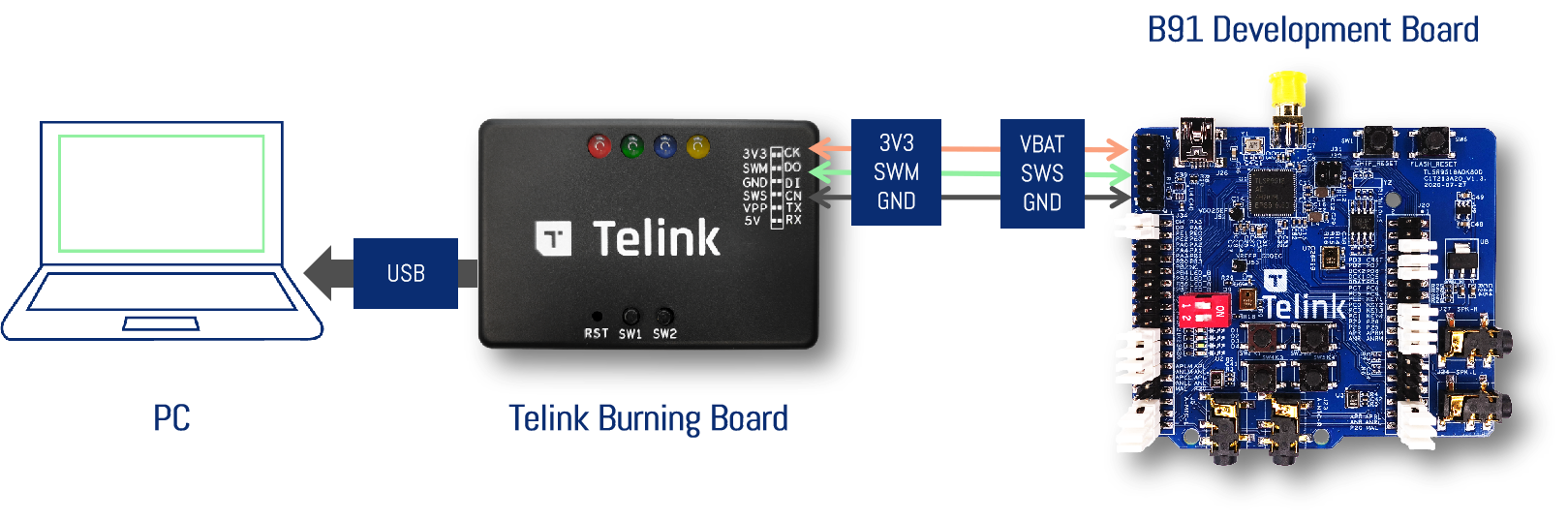
Power Connection Method 2
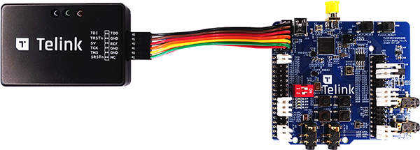
Step 1: The JTAG interface is located to the left of the mini USB interface. Please note “Telink” text orientation.
Step 2: Connect the TLSR9 DEV KEY to the JTAG interface using DuPont wires.
Step 3: With this connection in place, the Telink IDE tool can be used to download FW. Please ensure the DIP button is set correctly.
- The TLSR9 DEV KEY includes a 5V LDO.
- It is not necessary to have a USB connection if the TLSR9 DEV KEY is connected to TLSR9518ADK80D via DuPont wires.
- USB connection via USB cable is only necessary when using the USB function.
Dual Analog Microphone Function
The development board uses external audio input by default. If developers want to use the onboard AMICs, please set jumpers as shown in the picture below.
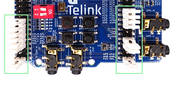
Jumper setting instructions:
- Move the jumpers of second to last and third to last on the both sides of the development board to the fourth to last and fifth to last positions respectively. (Move from LINE-IN pins to AMIC pins)
Audio Input Path (Encoding) Test
Test Items:
- THD+N (Total Hormonic Distortion + Noise)
- Frequency Response
- Signal to Noise Ratio
The Driver SDK has incorporated the audio test demo.
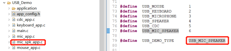
Compile the mic_spk demo in USB_DEMO and generate a performance test bin, After burning the bin file, the B91 development board will be recognized as a USB audio device with a combination of microphone and speaker.
| USB Device | Word Lengths | Channel | Sample Rates |
|---|---|---|---|
| Microphone | 16 bits | STEREO | 16K |
| Speaker | 16 bits | STEREO | 16K |
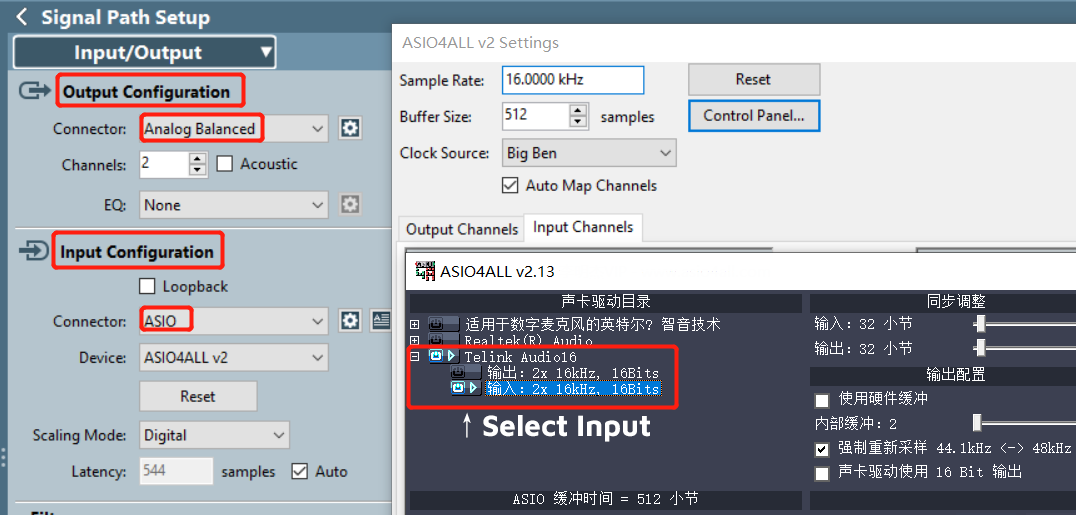
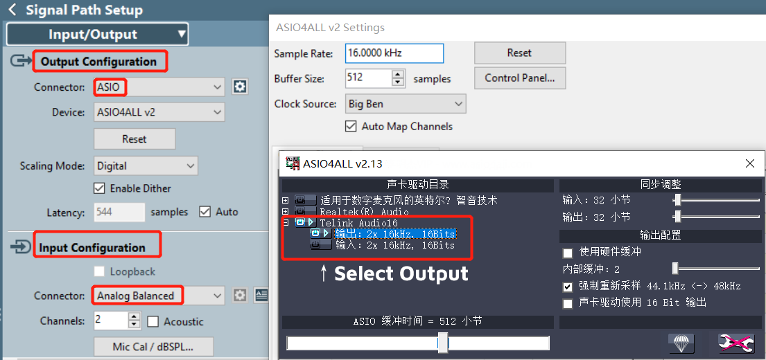
Keep the default setting of the jumpers, and use an audio analyzer for testing, such as APx525.

- The ASIO device is a microphone in the AP Input Configuration.
- To prevent microphone and speaker from interfering with each other, please disable the other device when enabling one device in the AP ASIO device control panel.
Audio Output Path (Decoding) Test
Test Items:
- THD+N (Total Hormonic Distortion + Noise)
- Frequency Response
- Signal to Noise Ratio
The Driver SDK has incorporated the audio test demo.
Compile the mic_spk demo in USB_DEMO and generate a performance test bin, After burning the bin file, the B91 development board will be recognized as a USB audio device with a combination of microphone and speaker.
| USB Device | Word Lengths | Channel | Sample Rates |
|---|---|---|---|
| Microphone | 16 bits | STEREO | 16K |
| Speaker | 16 bits | STEREO | 16K |
Keep the default setting of the jumpers, and use an audio analyzer for testing, such as APx525.
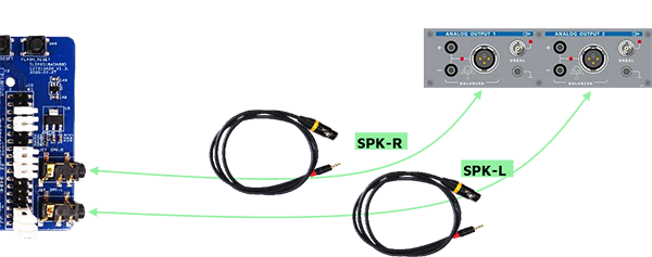
- the ASIO device is the speaker in the AP Output Configuration.
- To prevent microphone and speaker from interfering with each other, please disable the other device when enabling one device in the AP ASIO device control panel.
Audio Input/Output Path Demo
Test Items:
- Audio Encoding
- Audio Decoding
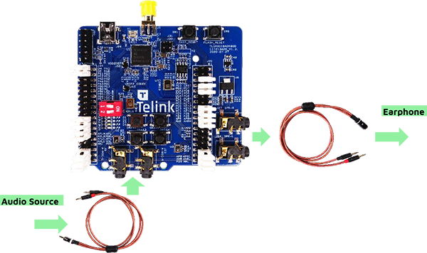
To enable the audio functionality during the development process, please connect as shown in the picture below.
GPIO Test
- All GPIO’s of TLSR9518A are connected to pins to facilitate testing.
- Please refer to design schematics for GPIO pin reference.
Reference Design
Please refer to the Telink wiki to access relevant design files click here
Bluetooth® Mesh + Local Voice Recognition Demo
Demo Introduction
The TELINK TLSR9 series chips support local keyword spotting (KWS) and command recognition, which is implemented by software algorithm and runs over the Bluetooth Mesh stack.
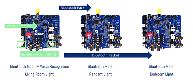
There are 3pcs of B91 Development Boards in this demo:
- The 1pc on the left is programmed to support voice recognition
- The 2pcs on the right are programmed to act as ordinary Bluetooth SIG Mesh nodes
Demo Features
- One Keyword + 8 ~ 20 command words: standard reference provided, customized keyword and command word can be trained with NRE cost
- No extra hardware needed
- Works with single mic, extensible to 2 mics with noise reduction
Configuring the Starter Kit
You can use the prebuilt binary for the following demo testing. It is already provided in the B91_SIG_Mesh_SDK.zip (\release_bin)
- 9518_mesh_speech.bin - Bluetooth Mesh + Voice Recognition
- 9518_mesh.bin - Bluetooth Mesh
Erase the chip flash, and program the B91 Development Board with .bin files respectively.
Install the “TelinkBleMesh” APP on Android mobile. (included in the B91_SIG_Mesh_SDK.zip, \app)
Device Networking
The Android APP defaults to manual provision mode.
- Open the “TelinkBleMesh” APP, click the “+” button in the upper right corner of the main interface to enter the “Device Scan”.
- The APP will automatically search for mesh devices. User can click the “ADD” button to add single device to the mesh network, or click the “X” button to ignore the device. The user can also click the “Add All” button at the bottom of the interface to add all devices at once.
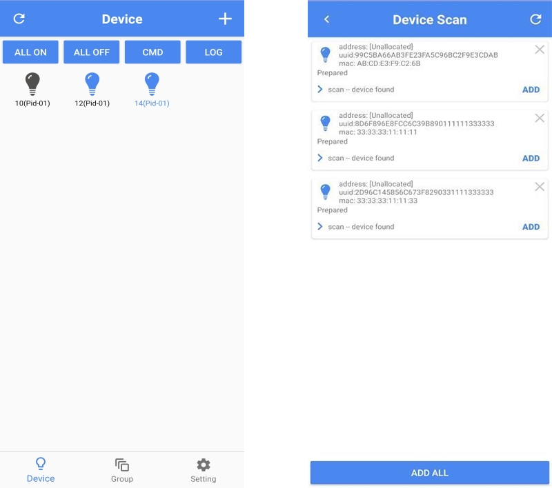
- Scan-device found folds the status of the scanned device, click the arrow on the left to expand the status of the networking process.
- There is a reload button in the upper right corner of the Device Scan interface. The device list can be refreshed in manual provision networking mode.
Device Setting
Long press the networked device icon to enter the Device Setting interface. The device can be grouped under the Group tab.
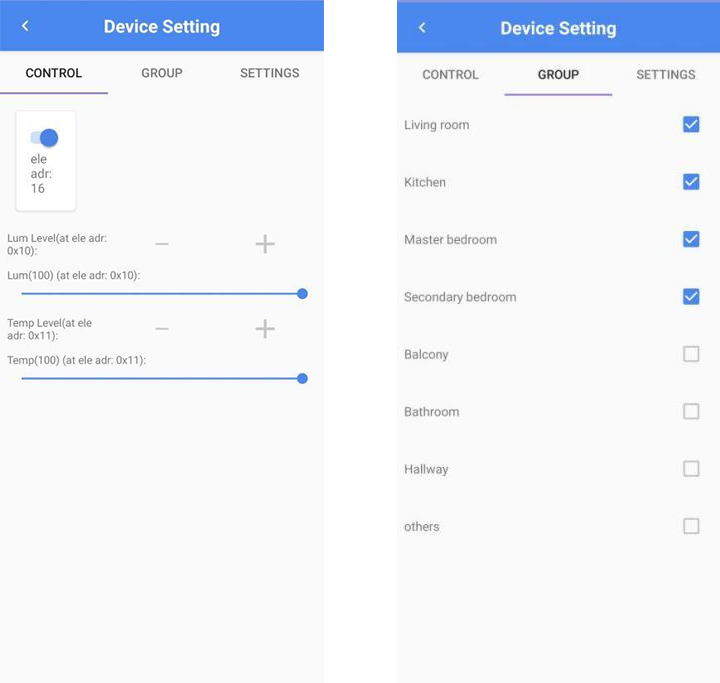
The currently supported voice commands include living room light, bedroom light and pendant light. The corresponding grouping setting are as follows:
- Living room - Living Room Light / 客厅灯
- Master bedroom - Bedroom Light / 卧室灯
- others - Pendant Light / 吊灯
Local Voice Recognition
Currently supports voice commands are as follows:
打开灯光
关闭灯光
打开吊灯
关闭吊灯
打开客厅灯
关闭客厅灯
打开卧室灯
关闭卧室灯
Remarks:
- The development board programmed with “9518_mesh.bin” has no voice function and can be placed outside the voice range to demonstrate the mesh effect.
- If developer uses the .bin file compiled from the SDK code, “SPEECH_ENABLE” needs to be turned on.
- The jumper of the development board for local voice recognition needs to be configured to enable the onboard AMICs.
Online Purchase
* The B91 Generic Starter Kit can be purchased online via Mouser or Taobao.
* Other Development Kits can also be obtained by contacting Telink.