Bluetooth® LE Telink Mesh
Conetents
Introduction
The TLSR8 series (TLSR825x/826x/827x) support Telink proprietary Bluetooth® Mesh, and they are covered in the same Telink mesh SDK. Telink Mesh is a proprietary mesh solution based on Bluetooth® LE technology, it can be used for various smart home and smart control applications such as lighting, sensors, controls, and switch.
Resources
| Part Number | Datasheet | SDK | Dev Kit | Hardware Design Guide | Reference Design |
|---|---|---|---|---|---|
| TLSR8269/8267/8261 | TLSR8269 TLSR8267 |
Telink Mesh | TLSR8269 Mesh Light HDK | TLSR826x Hardware Design Guide | TLSR8269 Dongle |
| TLSR8258/8253/8251 | TLSR8258 TLSR8253 TLSR8251 |
Telink Mesh | B85 Mesh Starter Kit | TLSR825X Hardware Design Guide | TLSR8258 Dongle TLSR8258 Mesh RCU |
| TLSR8278/8273/8271 | TLSR8278 TLSR8273 TLSR8271 |
Telink Mesh | TLSR8278 Generic Starter Kit | TLSR827X Hardware Design Guide | TLSR8278 Dongle |
Demo
Material List
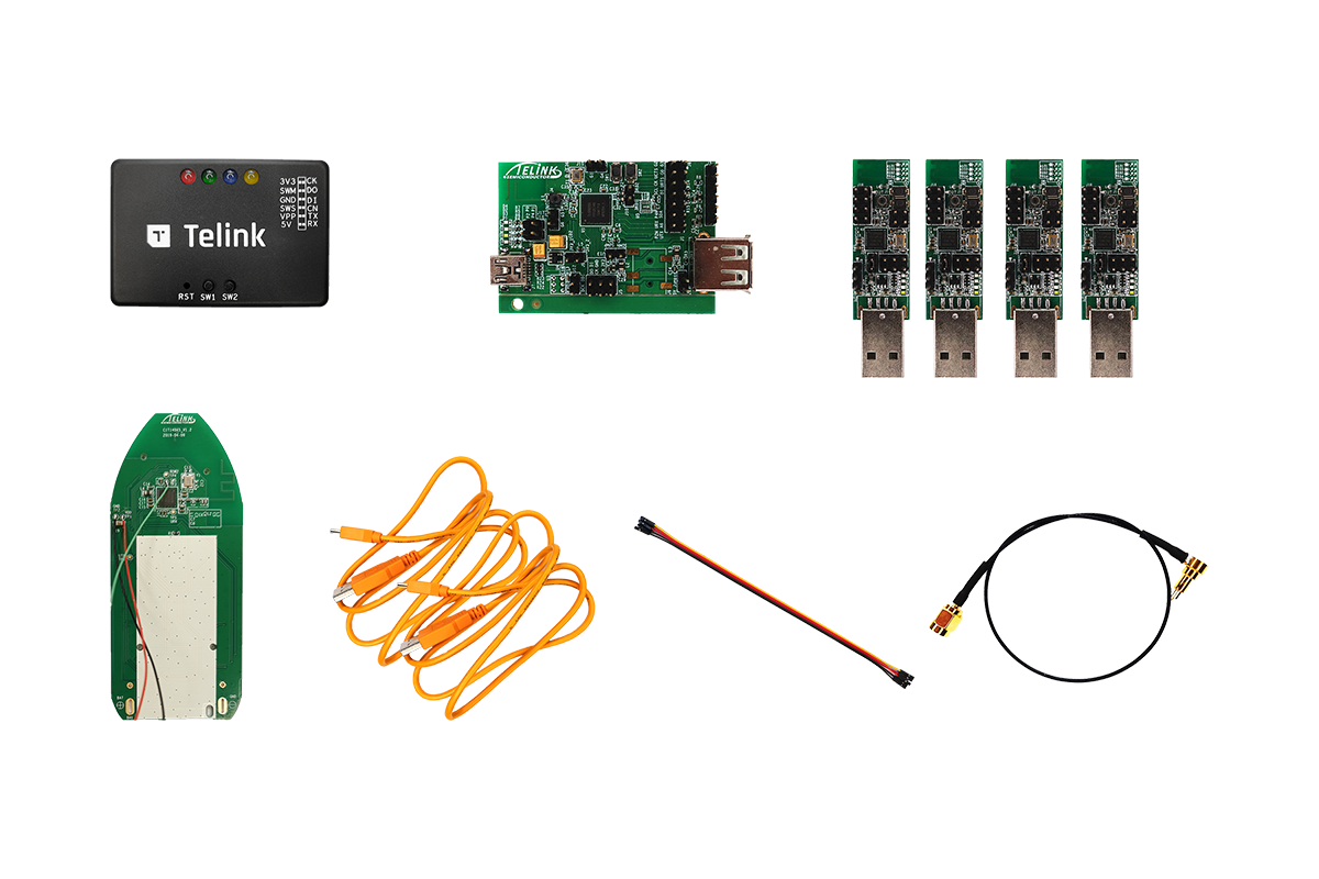
The typical Telink Bluetooth® Mesh Development Kit includes:
- Multiple USB dongles for emulating mesh nodes or gateways
- Remote control PCBA for emulating remote controller, wall switch, and also for demonstrating group controls
- Telink Burning Board
PC installed with
- TELINK BDT tool
- SIG Mesh Tool for controlling mesh nodes (included in the SIG Mesh SDK.zip, \tools)
Mobile installed with
- Reference Android or iOS APPs (included in the SIG Mesh SDK.zip, \app)
Features
The Telink Mesh demo uses lighting application as an example to demonstrate the mesh functionalities and is presented in 4 different ways:
- Node Control by APP with OTA
- Node Control by Gateway
- Node Control by Remote
- Node Control by Master Dongle
Quick Start
Configuring the Starter Kit
Demo required bin files are included in the “SDK and Tools” download firmware folder release zip.
For further info, please refer to the Developer Handbook for Telink Mesh SDK.
Node Control by APP with OTA
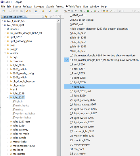
In this demo, two 8267 dongles are used to emulate light bulb node. Bin file is generated by “light_8267” project with “light_8267” compile option as indicated in following diagram.
Launch Telink “MeshDemo” app as shown in following page. The two blue colored light bulbs indicate the two demo dongle connecting with an iPhone in this example. Tapping the icon would toggle light on/off.
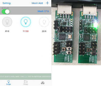
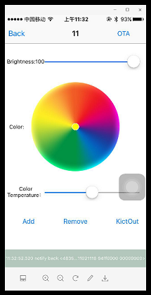
Holding bulb icon enters following control panel. Brightness and color temperature can be adjusted. Group assignment can be “Add” or “Remove”. Each node can even be “KickOut” of the mesh network connecting with APP. OTA can also be executed by selecting “OTA” on upper right corner.
Node Control by Gateway
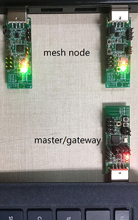
Node control by gateway demo requires 3 pieces of HW as shown below: 2 pieces of light bulb and 1 piece of gateway dongle,all by 8267.
8267 gateway dongle in this example is programmed by using “light_gateway” project in SDK and “light_gateway_8267” compile option; and light bulb bin is the same as in APP demo. After being programmed, gateway dongle must be plugged in USB port of PC and light bulbs can be powered by any USB port. The light bulbs, if has been provisioned previously, need to reset by having 3 short power cycling (on/off each 1s) followed by 2 long power cycling (on/off each 3-5s). Successful reset would trigger 3 blinks.
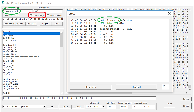
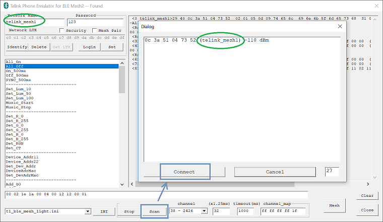
Now launch “tl_ble_phone_mesh2” tool under tools/telink-ble-phone/ dir. Click off “secuirity” check box. Then click on “Scan” followed by “Connect” to gateway itself labelled with “telink_mesh1”. Make sure the mesh network name is now “telink_mesh1”. Using “All_on” and “All_off” command on left pane would turn on/off the lights respectively.
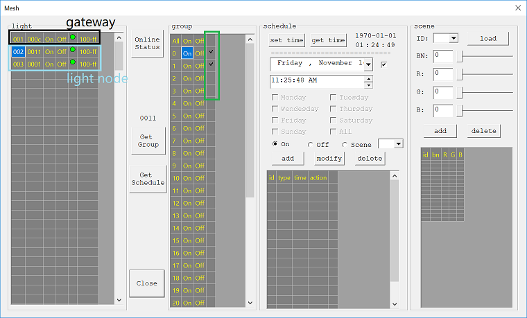
Now continue clicking on “Mesh” button. This will bring out the light control UI as shown below. Click on “Online Status”, light bulbs is listed in the “Mesh” pane on left side of the window with corresponding MAC address in blue rectangular, top one in black is gateway. By clicking on and highlight a specific light node, this particular light can be assigned to desired group by checking on green area. Once group assignment is done, each group can be turned off/on by itself.
Node Control by Remote
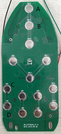
Continuing with the setup from “Node control with Gateway”, a 8269 remote as shown below is programmed by “light_switch” project in SDK using “light_switch_8269” compile option. Button A and B would turn all 2 lighting dongles on and off, respectively.
Node Control by Master Dongle
Now program the gateway dongle into master dongle using “ble_master” project in SDK and “ble_master_dongle_8267_69” compile option.
When launching PC tool, “security” box needs to be checked as shown below. Now “Scan” and “Connect” to the lighting node, and click “Login”. Lighting control and group assignment is the same as gateway demo.
“Network Name” can be changed followed by “Set”, 2 lighting nodes in this example needs to be done one by one.