B92 Generic Starter Kit Hardware Guide
Contents
Introduction
The guide introduces how to get started with the Kit. B92 Generic Starter Kit is a hardware platform which can be used to verify TLSR952x series chipset and develop many kinds of 2.4G protocol application, including Bluetooth basic rate (BR), enhanced data rate (EDR), low energy (LE), Bluetooth LE Mesh, 2.4 GHz proprietary, RFFE and Wi-Fi Coexistence Interface.The TLSR952x combines the features and functions needed for high quality wearable devices into a single System-on-Chip (SoC).
Material List
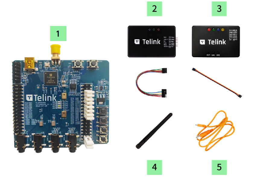
| Item | S/N | Product Name | Qty | Description |
|---|---|---|---|---|
| 1 | TLSR9528ADK88D | B92 Development Board | 1 | including jumpers |
| 2 | TLSRGSOCBK100B | TLSR9 DEV KEY | 1 | JTAG BURING EVK, including DuPont wires |
| 3 | TLSRGSOCBK56B | Telink Burning Board | 1 | SWS BURING EVK, including DuPont wires |
| 4 | Whip Antenna | 1 | 2.4Ghz antenna | |
| 5 | USB cable | 1 | USB A to mini USB |
Overview
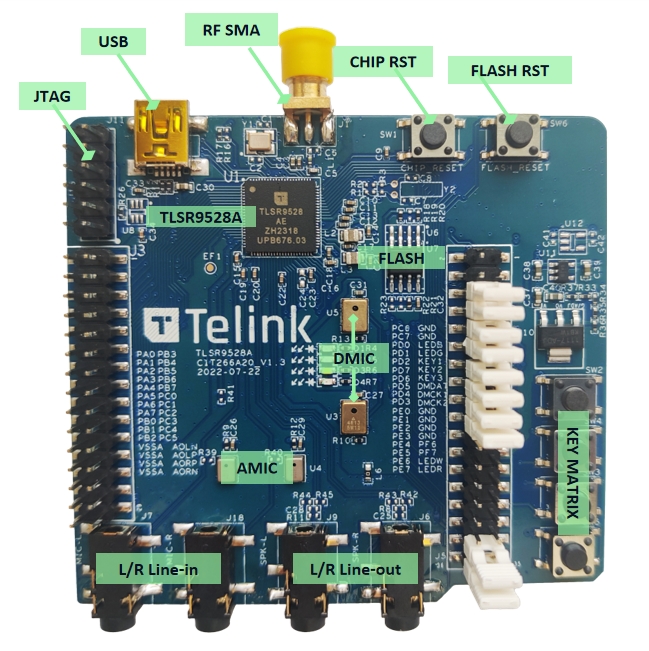
The diagram below illustrates main components and default jumper setting on TLSR9528ADK88D as shipped. It supports functions listed here in default setting:
- RF conducted test
- External Flash with reset button
- Chip reset button
- Mini USB interface
- 4 LED, Key matrix up to 4 keys
- 2 line-in function (dual analog microphone supported when switching jumper from microphone path)
- Dual digital microphone
- Stereo line-out
TLSR9528ADK88D Top View
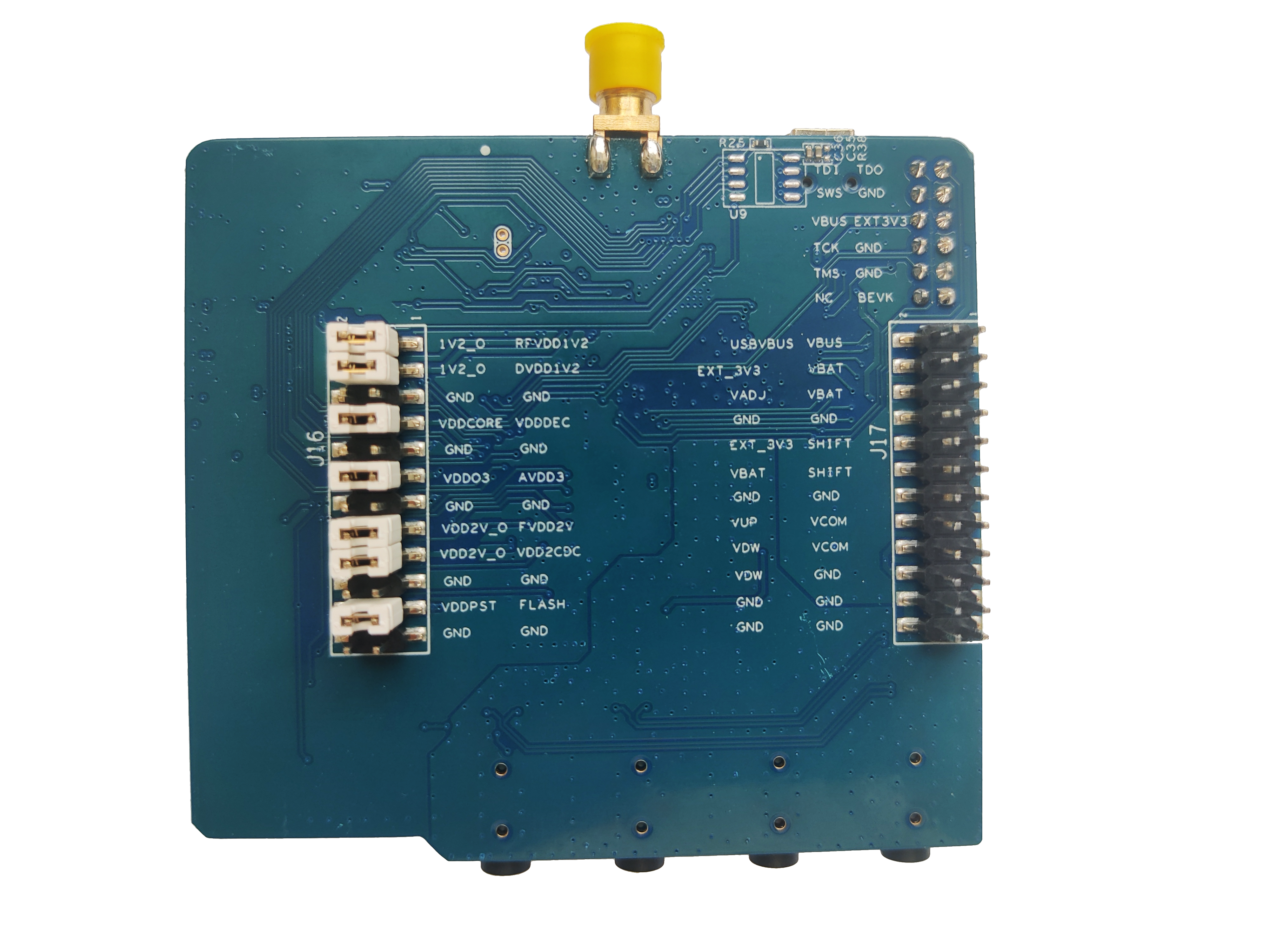
TLSR9528ADK88D Bottom View
Quick Start
Flash Programming
Developers can choose any of the following tools for flash programming.
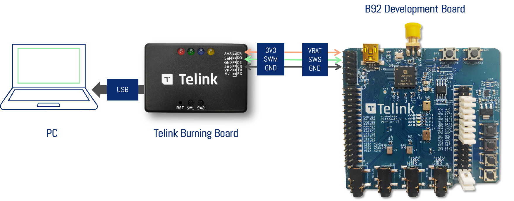
Power connection method with Telink Burning Board
TLSR9528A supports easy debug method. Only three wires are needed.
- 3.3V from Telink Burning Board is connected to VBAT from TLSR9528ADK88D.
- SWM from Telink Burning Board is connected to SWS form TLSR9528ADK88D.
- GND from Telink Burning Board is connected to GND form TLSR9528ADK88D.
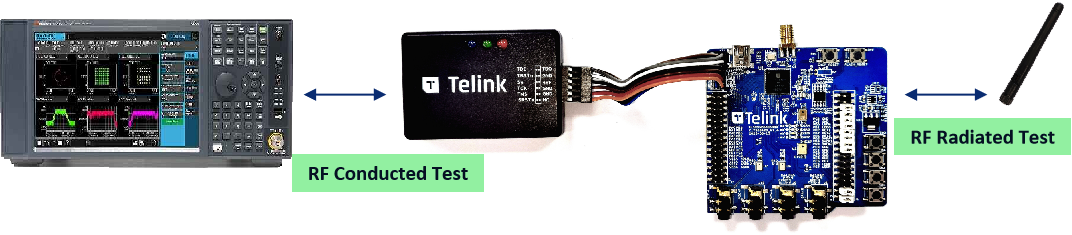
RF Test
Power on firstly, then connect RF SMA through cable to equipment or through whip antenna when verifying chipset or develop function. The corresponding tool is EMI tool which can be gotten from wiki.
Use the right bin and tool after checking the test instrument.
-
When using EMI tool and bin, user often use spectrum analyzer to do rf test.
-
When using BQB bin, user often use CMW500, MT8852B and so on to do rf test.
GPIO Test
- All of GPIOs of TLSR9528A have been connected to PINs.
- Then users can read the corresponding schematic and test all GPIOs.
- If the B92 series chip has the CFG pin, then you can adjust the power domain of GPIO. if the CFG pin is connected to VDDO3, power domain of GPIO is 1.8V; if the CFG pin is connected to GND, power domain of GPIO is 3.3V. In addition, the TLSR9528A does not have the CFG pin, so it cannot adjust the power domain of the GPIO. The power domain of the TLSR9528A’s GPIO is 3.3V.
Reference Design
Please refer to the Telink wiki to access relevant design files click here