Wireless Audio Streaming Solution for Soundbar/Speakers
Contents
Introduction
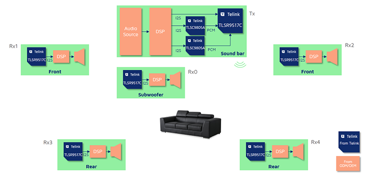
The Telink TLSR9 series support wireless audio streaming solution. The solution provides several key features that enable users to develop wireless soundbar or speaker sets. Telink offers ready-to-use development kit for immediate evaluation.
- Scalable architecture applicable to 1 Tx + up to 5 Rx systems
- Ultra-low latency
- Customized wireless transmission to achieve high channel bandwidth utilization and strong anti-interference ability
- High quality LE audio codec
- Precise synchronization among multiple Rx
- Adaptive sample rate transition
Resources
| Part Number | Demo Files | Dev Kit | Hardware Design Guide | Reference Design |
|---|---|---|---|---|
| TLSR9517C | Tx.bin Rx.bin |
B91 Generic Starter Kit | B91 Hardware Design Guideline | B91 Development Board |
Demo
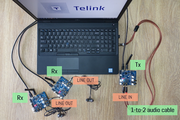
The demo below uses three Telink B91 Development Boards to simulate a soundbar, a subwoofer and a speaker, it is an 1 Tx + 2 Rx system. Developers can follow the steps to program the dev boards, make the correct configuration and and listen to the audio.
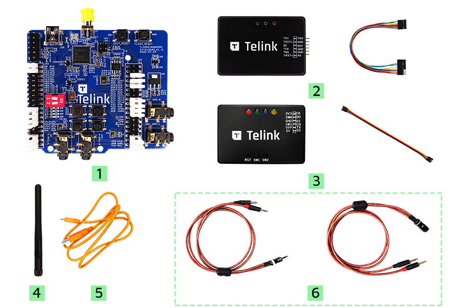
Material List
| Item | S/N | Product Name | Qty | Description |
|---|---|---|---|---|
| 1 | TLSR9518ADK80D | B91 Development Board | 1 | including jumpers |
| 2 | TLSRGSOCBK100B | TLSR9 DEV KEY | 1 | JTAG BURING EVK, including DuPont wires |
| 3 | TLSRGSOCBK56B | Telink Burning Board | 1 | SWS BURING EVK, including DuPont wires |
| 4 | Whip Antenna | 1 | 2.4Ghz antenna | |
| 5 | USB cable | 1 | USB A to mini USB | |
| 6 | Audio cable* | 2 | 3.5mm 1-to-2 audio cables (plug and jack) |
Remarks: The B91 Generic Starter Kit does not include audio cables (Item #6) as standard. For these add-ons, please consult with the Telink sales team.
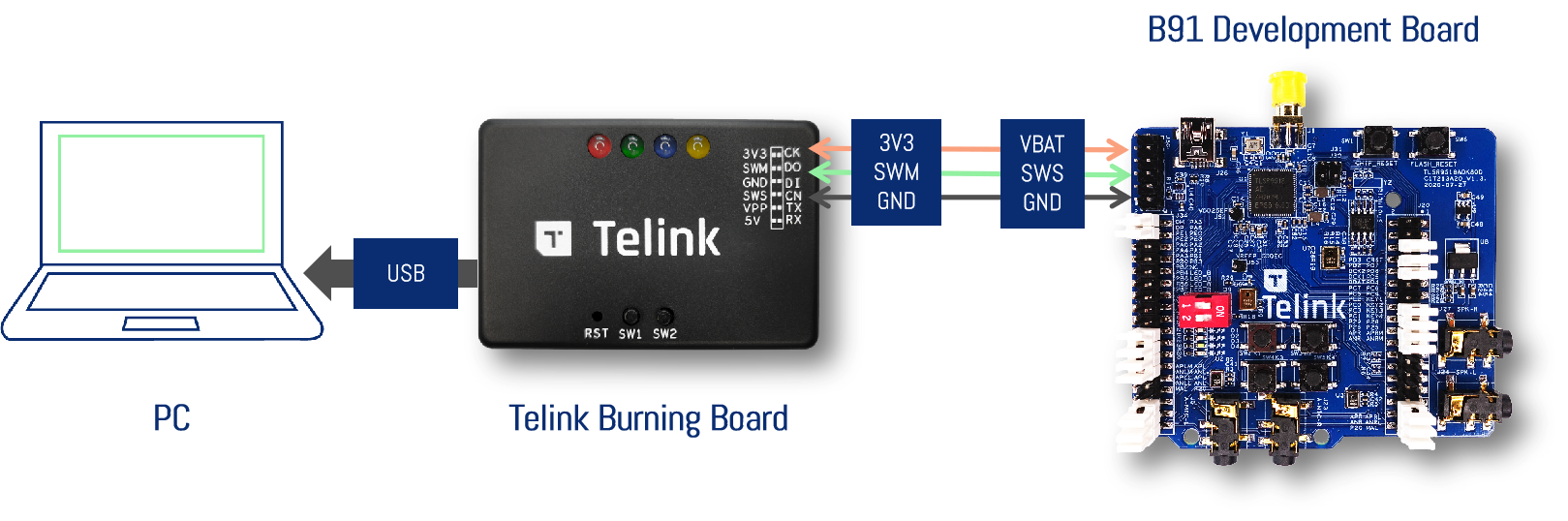
Configuring the B91 Development Boards
You can use the prebuilt binary for the following demo testing. Please contact Telink sales to obtain demo binary files.
- le_initiator.bin - the Tx device that simulates a Soundbar
- le_responder.bin - the Rx device that simulates Subwoofer or Speaker
It requires the latest TELINK BDT tool to program the target boards.
To complete this demo, you will need 3 pcs of B91 Development Boards, which are programmed to work as one Tx device and two Rx devices.
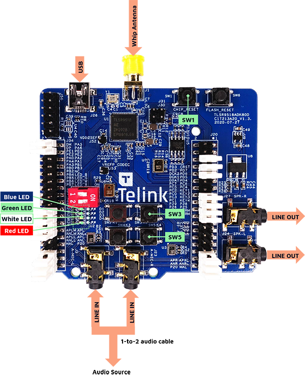
After the B91 Development Boards are successfully programmed, power on the development boards and check the status of the indicator lights.
- Tx device: Red LED is on.
- Rx device: Blue LED is on.
Left Channel Pairing
Step 1: Power on the Tx device and one of the Rx devices by USB cables.
Step 2: Press SW5 on the Rx device, then press SW1 on the Tx device to reset the chip, and they will be paired automatically.
Step 3: The Blue LED on the Rx device is on, while the Red and Blue LEDs on the Tx device are on.
Step 4: If the Blue, Green and Red LEDs on the Tx device light up at the same time after pairing, you need to press SW1 on the Tx device to do a reset. After resetting again, the Blue and Red LEDs will light up on the Tx device.
Right Channel Pairing
Step 1: Power on the Tx device and another Rx device by USB cables, and power off the 1st Rx device that has been paired. Now only the Red LED on the Tx device is on.
Step 2: Double press SW5 on the Rx device, then press SW1 on the Tx device to reset the chip, and they will be paired automatically.
Step 3: The Blue LED on the Rx device is on, while the Red and Green LEDs on the Tx device are on.
Step 4: If the Blue, Green and Red LEDs on the Tx device light up at the same time after pairing, you needs to press SW1 on the Tx device to do a reset. After resetting again, the Red and Green LEDs will light up on the Tx device.
Pairing Completed
Power on the paired Tx and Rx devices at the same time, the Blue, Green and Red LEDs on the Tx device are on. The Tx device is connected to the both Rx devices now.
Audio Playback Test
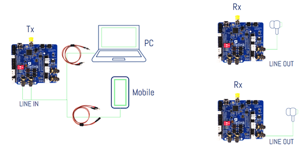
Step 1: PC outputs stereo audio source through 3.5mm audio socket.
Step 2: Separate the left and right channel audio through the 1-to-2 audio cable.
Step 3: Connect the left and right channel audio to the Tx device: L/R MIC LINE IN audio socket.
Step 4: The Rx devices will play the left and right channel audio signals respectively, you can plug the earphones into the LINE OUT audio socket to hear the sound.
- You can also use mobile as a stereo audio source to verify the audio playback function.
Remarks: The B91 development board supports multiple audio input methods. The development board uses external audio input by default. If the developer wants to use the onboard AMIC, please refer to the Jumper Setting of Dual Analog Microphone.